
Portable electronic module with back cover changing function

a technology of electronic modules and functions, applied in the direction of electrical apparatus construction details, instruments, electrical apparatus casings/cabinets/drawers, etc., can solve the problem of difficult replacement of back covers, and achieve the effect of improving the flexibility of use and difficult replacemen

Active Publication Date: 2014-10-14
WISTRON CORP
View PDF43 Cites 4 Cited by
  • Summary
  • Abstract
  • Description
  • Claims
  • Application Information

AI Technical Summary

Benefits of technology

Facilitates quick and easy replacement of the back cover, improving flexibility and reducing the time and effort required for assembly and disassembly, while maintaining structural integrity and protection functions.

Problems solved by technology

However, in the said configuration, if a condition occurs that the back cover is needed to replace (e.g. a user wants to replace the back cover with another back cover of other different color according to his likes) or the back cover is damaged, the back cover can only be replaced after the bezel, the liquid crystal module and the related components are detached from the back cover sequentially, so as to cause a time-consuming and strenuous assembly and disassembly process and make the back cover difficult to replace.

Method used


Image

  • Portable electronic module with back cover changing function
  • Portable electronic module with back cover changing function
  • Portable electronic module with back cover changing function

Examples


Embodiment Construction

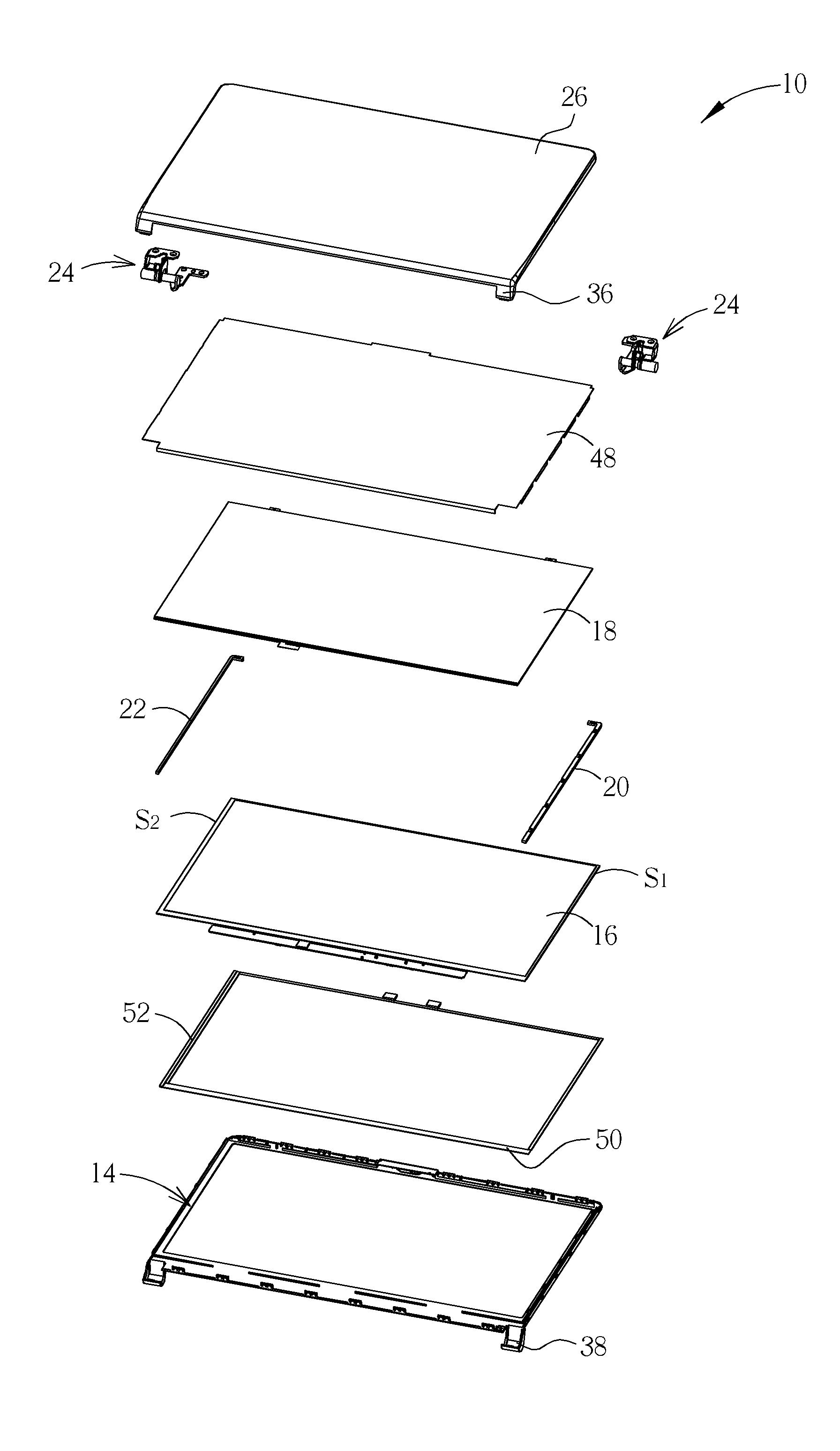
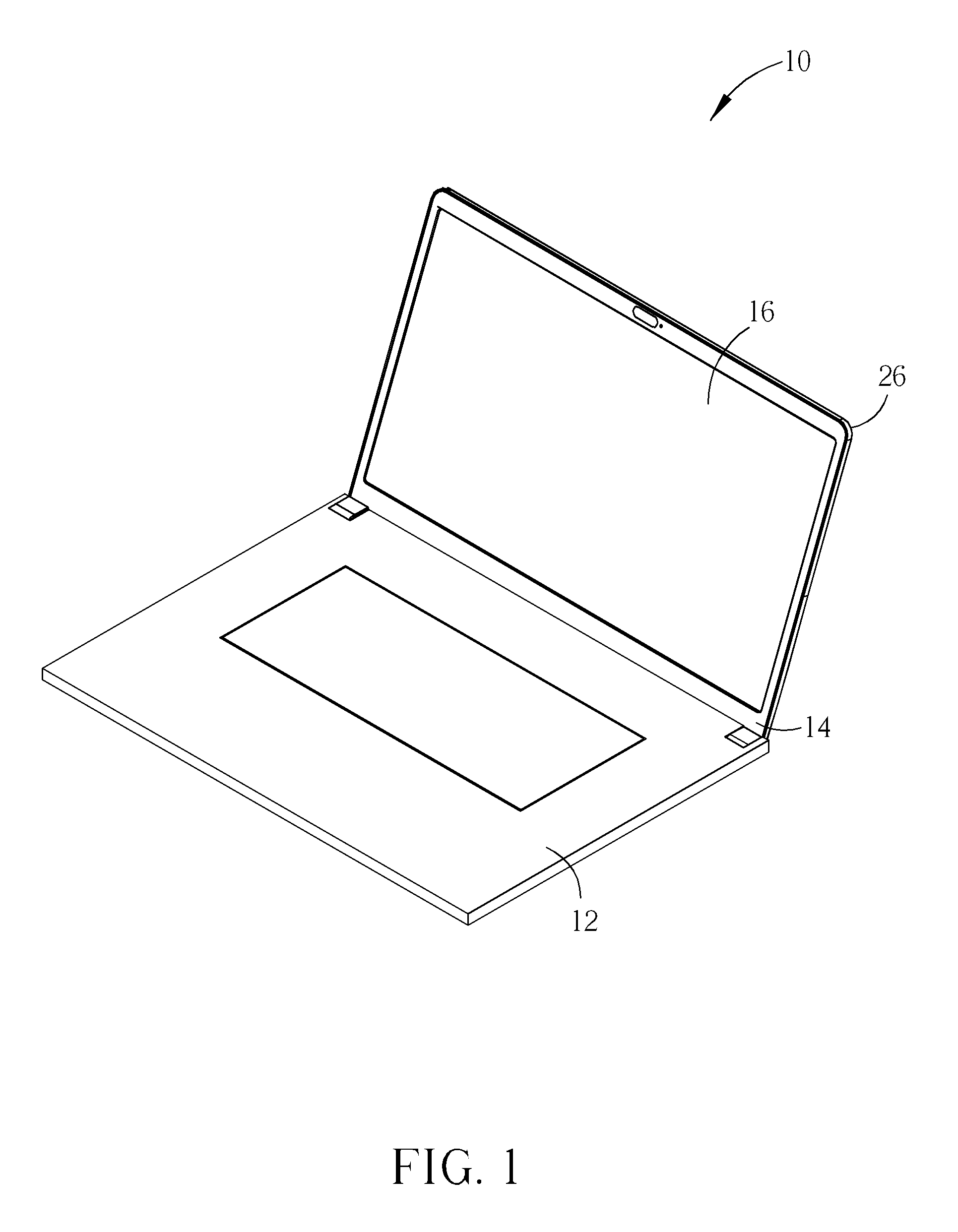
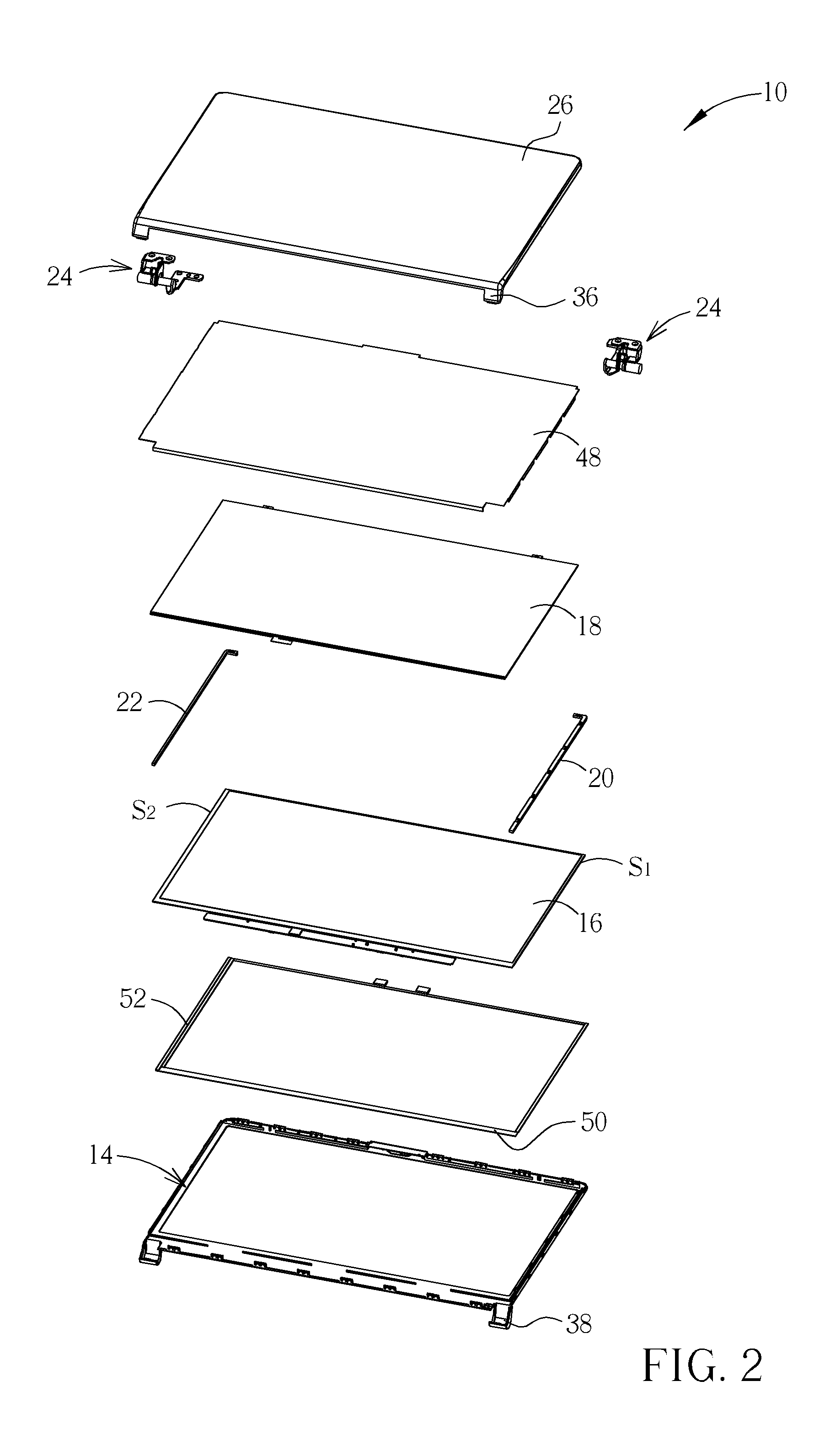
[0029]Please refer to FIG. 1 and FIG. 2. FIG. 1 is a diagram of a portable electronic module 10 according to an embodiment of the present invention. FIG. 2 is a partial exploded diagram of the portable electronic module 10 in FIG. 1. As shown in FIG. 1 and FIG. 2, the portable electronic module 10 includes a host device 12, a bezel 14, a glass panel device 16, a backlight device 18, a first limiting member 20, a second limiting member 22, at least one shaft member 24 (two shown in FIG. 2), and a back cover 26. The host device 12 is electrically connected to the glass panel device 16 and the backlight device 18 for performing display control of the portable electronic module 10. In this embodiment, the host device 12 can include components applied to a conventional computer host, such as a motherboard, a central processing unit, and a keyboard. The glass panel device 16 is fixed onto the bezel 14. The glass panel device 16 includes display components in a conventional liquid crystal ...


PUM


Abstract

A portable electronic module includes a bezel, a glass panel device, a first limiting member, a backlight device, a second limiting member, and a back cover. The glass panel device is fixed onto the bezel. The first limiting member is disposed at a first side of the glass panel device. The backlight device is disposed on the glass panel device. The second limiting member is disposed at a second side of the glass panel device for limiting the backlight device cooperatively with the first limiting member. The back cover covers the backlight device and is detachably connected to the bezel for containing the glass panel device and the backlight device cooperatively with the bezel.

Description

BACKGROUND OF THE INVENTION[0001]1. Field of the Invention[0002]The present invention relates to a portable electronic module, and more specifically, to a portable electronic module with a back cover changing function.[0003]2. Description of the Prior Art[0004]For a portable computer, a conventional configuration for a bezel, a back cover, and a liquid crystal module is to assemble the modularized liquid crystal module, related components (e.g. a dustproof film, a buffer film), and the bezel onto the back cover sequentially in a top-to-down manner. Accordingly, the liquid crystal module and the related components can be packaged between the bezel and the back cover.[0005]However, in the said configuration, if a condition occurs that the back cover is needed to replace (e.g. a user wants to replace the back cover with another back cover of other different color according to his likes) or the back cover is damaged, the back cover can only be replaced after the bezel, the liquid crysta...

Claims


Application Information

Patent Timeline
Patent Type & Authority Patents(United States)
IPC IPC(8): G06F1/16
CPCG06F1/1681G06F1/1637
Inventor TSAI, SONG-NINELIU, CHENG-SHINGLIU, JEN-HAO
Owner WISTRON CORP
Learn More