Connectors for separable firing unit assemblies, separable firing unit assemblies, and related methods

a technology of connecting components and firing units, applied in the direction of electric fuzes, lighting and heating apparatus, ammunition fuzes, etc., can solve the problems of increasing the inductance of the firing circuit, igniting explosive materials, and undesirable separability of the firing uni

Active Publication Date: 2014-10-21
NORTHROP GRUMMAN SYST CORP
View PDF35 Cites 51 Cited by
  • Summary
  • Abstract
  • Description
  • Claims
  • Application Information

AI Technical Summary

Problems solved by technology

When the electronics assembly in the firing unit is activated, the electronics assembly activates the initiation device, which causes ignition of the explosive material.
However, the separability of the firing unit may be undesirable in some instances because the ability to remove the electronics assembly from the initiation device may compromise or deteriorate the electronic connections between the firing unit and the initiation device.
For example, use of a separable electrical connection between the electronics assembly and the initiation device may increase the inductance of the firing circuit.
An increase in the inductance of a firing circuit may be undesirable in such systems employing a high voltage firing unit (HVFU).
For example, an initiation device such as an exploding foil initiator (EFI) may require a relatively large amount of voltage and current from the electronics assembly to ignite the EFI.
Increasing the inductance of the firing circuit may compromise the ability of the electronics assembly to reliably ignite the EFI, decreasing the reliability and safety of the firing unit.
Furthermore, a separable electrical connection between the electronics assembly and the initiation device may compromise the ability of the firing unit to be sealed from a surrounding environment in certain applications where such a seal is desirable.
Finally, a separable electrical connection between the electronics assembly and the initiation device may undesirably increase any, some, or all of size, weight, and cost of the firing unit, which may be especially undesirable where the firing unit is implemented in systems utilized in aerospace flight.

Method used


Image

  • Connectors for separable firing unit assemblies, separable firing unit assemblies, and related methods
  • Connectors for separable firing unit assemblies, separable firing unit assemblies, and related methods
  • Connectors for separable firing unit assemblies, separable firing unit assemblies, and related methods

Examples


Embodiment Construction

[0025]The illustrations presented herein are not meant to be actual views of any particular connector, firing unit assembly, or component thereof, but are merely idealized representations employed to describe illustrative embodiments. Thus, the drawings are not necessarily to scale and relative dimensions may have been exaggerated or understated for the sake of clarity. Additionally, elements common between figures may retain the same or similar numerical designation.

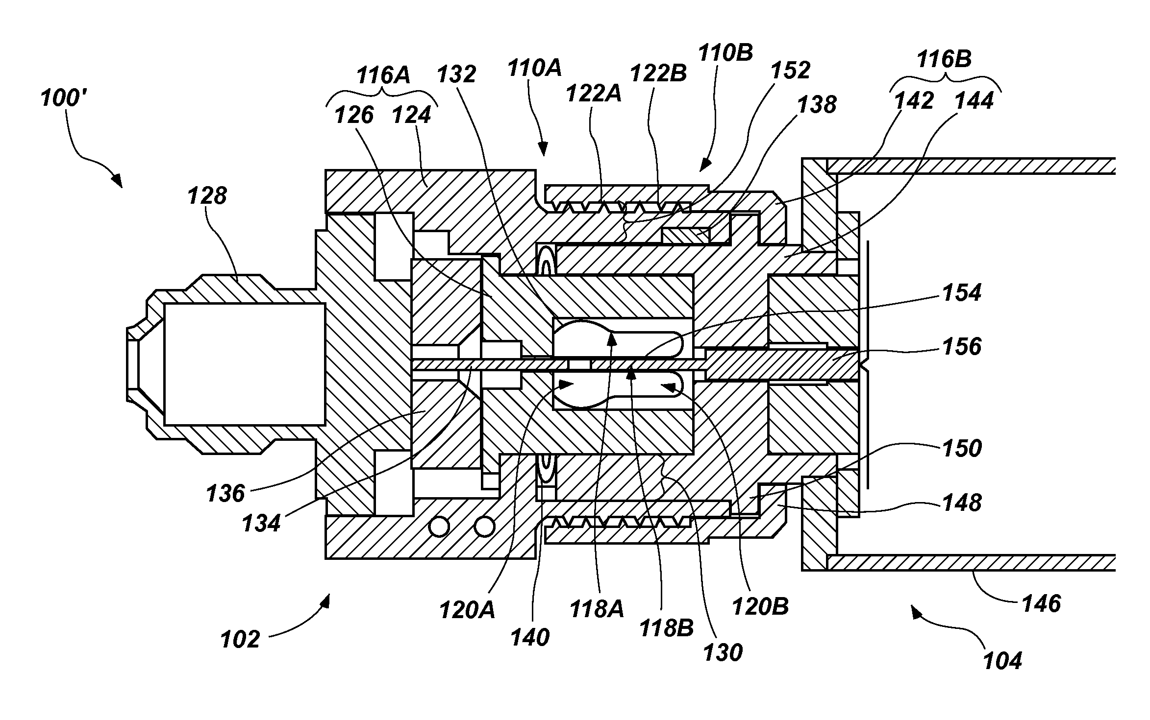
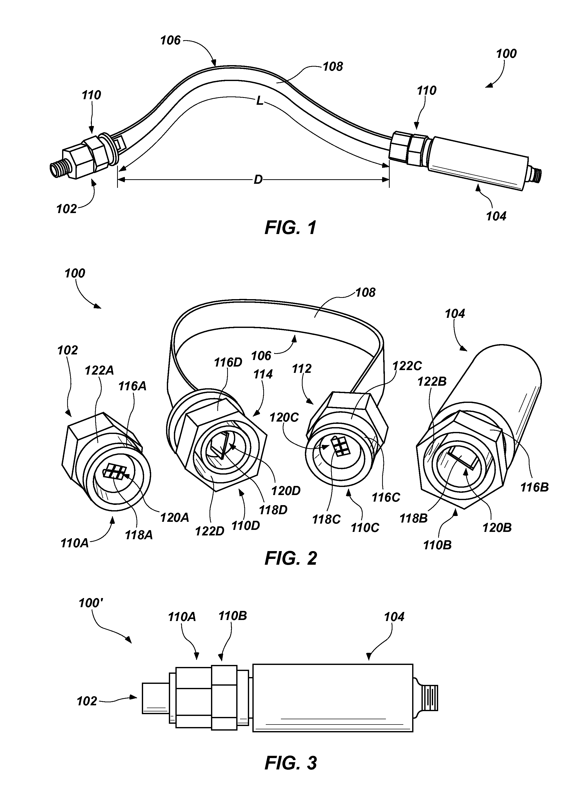
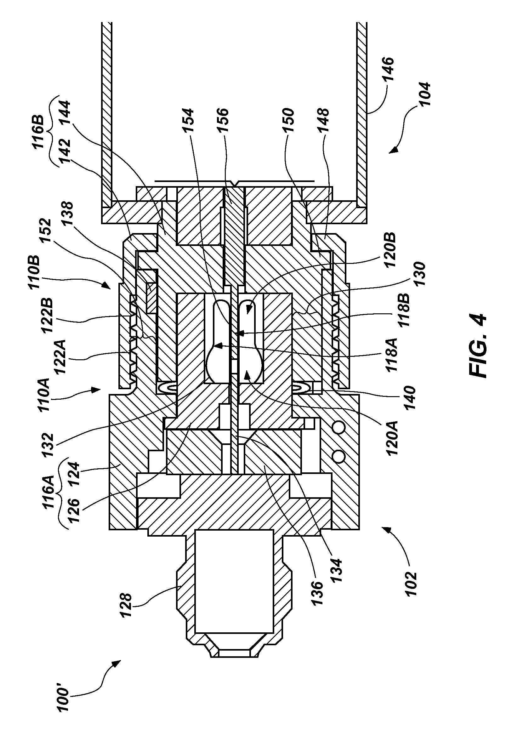
[0026]Disclosed embodiments relate generally to separable firing unit assemblies including connectors that enable initiation devices to be removed from electronics assemblies. More specifically, disclosed are connectors for connecting initiation devices to electronic assemblies that enable disconnection of the initiation devices from the electronics assemblies and do not significantly degrade a firing pulse transmitted through the connectors.

[0027]Firing unit assemblies may be integrated or utilized with various types o...


PUM

PropertyMeasurementUnit
inductanceaaaaaaaaaa
lengthaaaaaaaaaa
lengthaaaaaaaaaa

Abstract

Connection cables for separable firing unit assemblies comprise a first mating connector at a first end and a second mating connector at a second, opposing end. A stripline cable electrically connects the first mating connector to the second mating connector. Separable firing unit assemblies comprise an initiation device. An electronics assembly is configured to transmit a firing pulse to the initiation device. One of a first mating connector and a second mating connector is coupled to the initiation device and the other of the first mating connector and the second mating connector is coupled to the electronics assembly. A second housing of the second mating connector is configured to receive a portion of a first housing of the first mating connector therein.

Description

FIELD[0001]The disclosure relates generally to firing unit assemblies for munitions systems. More specifically, disclosed embodiments relate to separable firing unit assemblies including connectors that enable initiation devices to be safely and easily removed from electronics assemblies.BACKGROUND[0002]There are many applications in which a firing unit is utilized to initiate or detonate explosive or pyrotechnic materials for actuation or detonation of a device or system. Examples include such things as weapon systems, aerospace systems such as rocket motors, airbag initiators, parachute harness connectors, and other systems. Firing units utilized in weapon systems, aerospace systems, and other systems typically include an electronics assembly and an initiation device. Such explosive or pyrotechnic materials may be ignited in several different ways. Typically, explosive materials have been ignited by flame ignition (e.g., fuzes or ignition of a priming explosive), impact (which oft...

Claims


Application Information

Patent Timeline
Patent Type & Authority Patents(United States)
IPC IPC(8): F42B3/10H01R11/11F42C19/12H01R43/26
CPCF42C19/06F41A19/69Y10T29/49174Y10T29/49208F42D1/045F42C19/12
Inventor DEVRIES, DEREK R.MADSEN, BRENT D.PETERSON, ELDON C.JACKSON, DONALD L.THORUP, WILLIAM W.
Owner NORTHROP GRUMMAN SYST CORP
Why Eureka
Try Eureka