Propeller shaft and constant velocity universal joint used therein

a technology of propeller shaft and constant velocity, which is applied in the direction of manufacturing tools, couplings, transportation and packaging, etc., can solve the problems of increasing the production cost of the vehicle, affecting the fit of the boot to the desired position of the propeller shaft,

Active Publication Date: 2014-10-21
HITACHI ASTEMO LTD
View PDF5 Cites 23 Cited by
  • Summary
  • Abstract
  • Description
  • Claims
  • Application Information

AI Technical Summary

Benefits of technology

[0009]Accordingly, the present invention is provided by taking the above-mentioned drawbacks of the conventional technology into consideration and aims to provide a propeller shaft that is free of the above-mentioned drawbacks.
[0011]In accordance with a second aspect of the present invention, there is provided a propeller shaft which comprises an inner cylindrical member having a center through bore, the center through bore having a splined cylindrical inner wall with which a splined cylindrical outer wall of a shaft is engaged; an outer cylindrical member disposed around the inner cylindrical member; a torque transmitting unit installed between the inner and outer cylindrical members to transmit a torque between the inner and outer cylindrical members; a sleeve member coaxially connected to the center through bore of the inner cylindrical member, the sleeve member permitting passage of the splined cylindrical outer wall of the shaft therethrough before effecting the engagement between the splined cylindrical outer wall of the shaft and the splined cylindrical inner wall of the inner cylindrical member; a flexible boot unit having one end fixed to the outer cylindrical member and the other end fixed to the sleeve member thereby to hermetically close one open side of an interior of the outer cylindrical member, the interior containing therein a grease; a seal ring arranged between the sleeve member and the shaft to suppress entry of foreign matter into the center through bore of the inner cylindrical member; and a positioning mechanism that effects a relative axial positioning between the shaft and the inner cylindrical member when the splined cylindrical outer wall of the shaft is inserted through the sleeve member into a given position of the center through bore of the inner cylindrical member.

Problems solved by technology

That is, it often happens that fitting the boot to a desired position of the propeller shaft takes a lot of time due to a complicated fitting process.
As will be understood from the above, such fitting process is troublesome and thus takes a lot of time thereby causing increase in production cost of the vehicle.

Method used


Image

  • Propeller shaft and constant velocity universal joint used therein
  • Propeller shaft and constant velocity universal joint used therein
  • Propeller shaft and constant velocity universal joint used therein

Examples


first embodiment

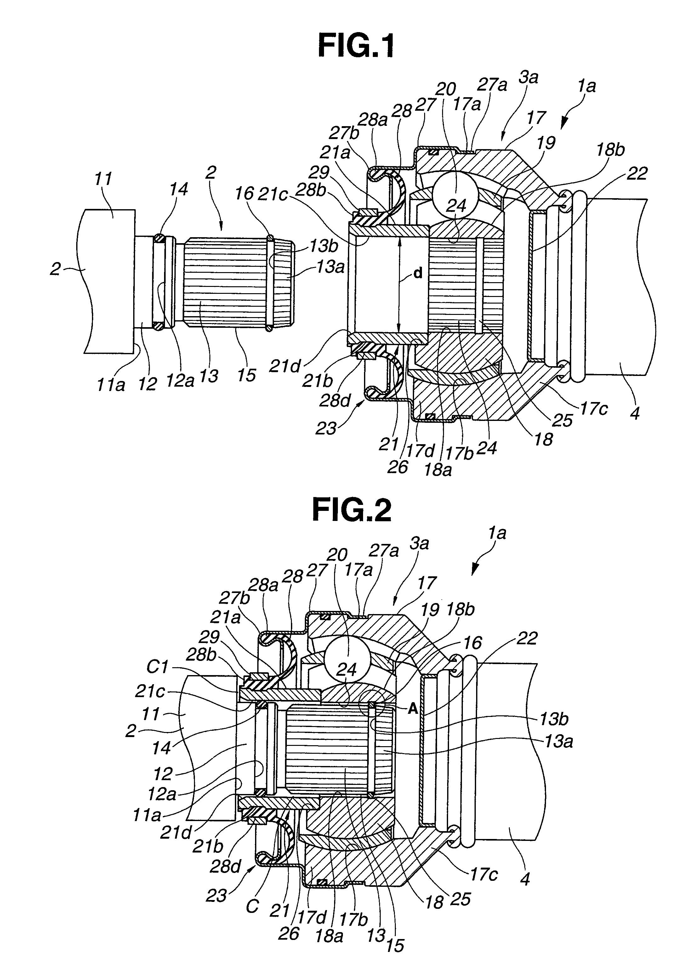
[0025]Referring to FIGS. 1 to 4, there is shown a propeller shaft is which is the present invention.

[0026]As is seen from FIG. 4, propeller shaft 1a comprises an input shaft 2 of steel that is adapted to connect to an output shaft of a transmission (not shown) mounted on a motor vehicle, a drive shaft 4 of aluminum alloy that is connected to input shaft 2 through a first constant velocity universal joint 3a, a driven shaft 6 of aluminum alloy that is connected to drive shaft 4 through a second constant velocity universal joint 5 and an output shaft 8 of steel that is connected to driven shaft 6 through a third constant velocity universal joint 7 and connected to an input shaft of a differential gear (not shown). As shown, when propeller shaft is practically used, a center bearing 9 holding an axially given portion of propeller shaft is supported by a vehicle body “VB” through a bracket 10. In the illustrated embodiment, center bearing 9 holds a right end of drive shaft 4 at a positi...

second embodiment

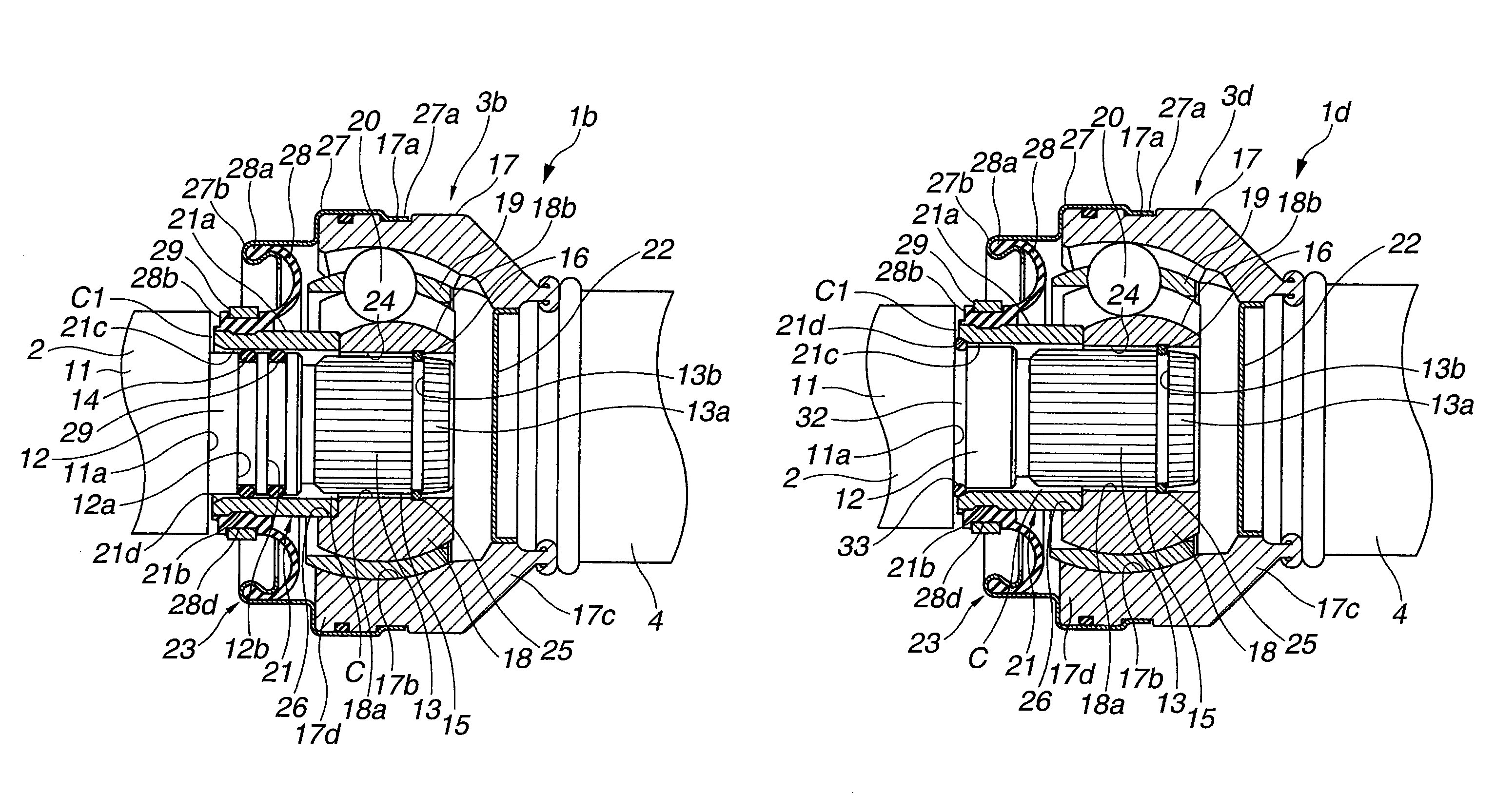
[0070]Referring to FIG. 5, there is shown a front assembly of a propeller shaft 1b which is the present invention.

[0071]Since this second embodiment is similar to the above-mentioned first embodiment, only parts or portions that are different from those of the first embodiment will be described in the following.

[0072]As is seen from FIG. 5, in this second embodiment, in addition to annular groove 12a, another annular groove (viz., second annular groove) 12b is provided by medium diameter intermediate portion 12 of input shaft 2. A second seal ring 29 is tightly held by second annular groove 12b. Like the seal ring 14, second seal ring 29 is pressed against the smoothed cylindrical inner surface of sleeve member 21.

[0073]Because of usage of two seal rings 14 and 29, much effective sealing against muddy water, dusts or the like is obtained in this embodiment. Furthermore, due to provision of such two seal rings 14 and 29, undesired leakage of the grease from the interior of outer cyli...

third embodiment

[0074]Referring to FIG. 6, there is shown a front assembly of a propeller shaft 1c which is the present invention.

[0075]In this third embodiment, the axial length of medium diameter intermediate portion 12 of input shaft 2 is small as compared with those of the above-mentioned first and second embodiments.

[0076]Furthermore, in this third embodiment, a seal ring 31 is tightly received in an annular groove 30 that is formed on the smoothed inner cylindrical wall of sleeve member 21. In use, seal ring 31 is pressed against the cylindrical outer surface of medium diameter intermediate portion 12 of input shaft 2.


PUM


Abstract

A propeller shaft is proposed which comprises an inner cylindrical member that has a center through bore into which a shaft is inserted; an outer cylindrical member disposed around the inner cylindrical member; a torque transmitting unit operatively disposed between the inner and outer cylindrical members; a sleeve member coaxially connected to the center through bore of the inner cylindrical member; a boot unit arranged to hermetically close one open side of an interior of the outer cylindrical member; and a positioning mechanism that effects a relative axial positioning between the shaft and the inner cylindrical member when a splined cylindrical outer wall of the shaft is inserted through the sleeve member into a given position of a splined cylindrical inner wall of the center through bore of the inner cylindrical member.

Description

BACKGROUND OF THE INVENTION[0001]1. Field of the Invention[0002]The present invention relates to a propeller shaft and a constant velocity universal joint used therein, which are used in wheeled motor vehicles.[0003]2. Description of the Related Art[0004]Usually, the propeller shaft for the wheeled motor vehicle has a split construction including a drive shaft that is adapted to connect to an output shaft of a transmission, a driven shaft that is adapted to connect to a differential gear and a coupling device, such as, constant velocity universal joint, Cardin joint or the like, that is operatively disposed between mutually facing ends of the drive and driven shafts. In practical use, an axially middle portion of the propeller shaft is rotatably held by a support device fixed to a body of the vehicle. Furthermore, for holding a grease in the coupling device, there is provided a boot between the drive shaft and the coupling device.[0005]One of such boots is disclosed by U.S. Pat. No....

Claims


Application Information

Patent Timeline
Patent Type & Authority Patents(United States)
IPC IPC(8): F16D1/116F16D3/223F16B21/18F16C1/04F16D3/84
CPCF16B21/183F16D2003/22313F16D2300/08F16D1/116F16D3/223Y10S464/906F16D3/845F16C1/04Y10T403/7033F16D2001/103B60K17/24F16D3/2055F16D3/387F16D2003/22303F16D2003/22326
Inventor SUGIYAMA, KENICHIKUROHA, TAKAHIROKOMAI, HIROMICHIMABE, YASUTOMOAKITA, YASUSHI
Owner HITACHI ASTEMO LTD
Why Eureka
Try Eureka