Retractable syringe with a cutting crown

a syringe and crown technology, applied in the field of syringes, can solve the problems of fluid leaking through, undesirable for the same needle of the syringe assembly to be used for multiple patients, and the hand of the doctor or nurse will become tired, so as to prevent reuse or recycling

Inactive Publication Date: 2014-10-21
INTUITIVE CREATIONS PTE
View PDF9 Cites 5 Cited by
  • Summary
  • Abstract
  • Description
  • Claims
  • Application Information

AI Technical Summary

Benefits of technology

[0013]The first aspect of the invention proposes in general terms that in a retractable syringe of the kind including a needle unit, a barrel, a plunger movable within the barrel towards the needle unit, a drive mechanism for driving the needle unit into the barrel, and a retention mechanism for retaining the needle unit with respect to the barrel, the plunger has a cutting crown at its forward end, for cutting the retention mechanism as the plunger is advanced, so that the drive mechanism retracts the needle unit into the barrel. The profile of the cutting crown includes one or more cutting teeth which cut a first portion of the retention mechanism before other portions of the cutting crown cut other portions of the retention mechanism. In other words, a user does not have to apply sufficient force to the plunger simultaneously to break all portions of the retention mechanism. This reduces the required activating force.
[0030]allowing for a tamper proof design that may prevent reuse or recycling.

Problems solved by technology

The force required should not be very great, or the doctor or nurse's hand will become tired if many injections are performed.
Furthermore, it is often undesirable for the same needle of the syringe assembly to be used for multiple patients, and several forms of syringe assemblies are known which prevent or discourage this.
When this happens, it is undesirable to have fluid leaking through the junction where the circumference of the front face of the plunger meets the walls of the barrel.
Unfortunately, the needle assemblies are prone to loosening and dropping off the syringe unit.
The Luer Lock however has a complicated design involving multiply nested interlocking portions.
Both these syringe assemblies contain a large amount of dead space—i.e. volumes in the syringe assembly which contain medicament which cannot be expelled from the syringe assembly.
There is typically dead space within the connector unit and / or the interface between the connector unit and syringe unit.
This dead space is an issue of concern as the cost of medicament may be high.
It is possible to reduce the size of the dead space by reducing the tolerances in the production process, but this increases the production cost of the syringe assembly.
Therefore, most designs of retractable syringe have dead spaces, resulting in wastage of the medicament.
In some designs air may be trapped in the dead space, and is hard to expel this air before the syringe assembly is used.
Furthermore, since the retention mechanism has to be strong enough to resist the urging force generated by the drive mechanism, the user has to apply an inconveniently large force to break the retention mechanism, and release the needle unit.
Furthermore, the needle unit, syringe unit, retention mechanism and drive mechanisms of many known retractable syringes have too many parts, leading to high production cost.
Since retractable syringes are expensive, some operatives are tempted to try to re-use them, and there is little to prevent this since almost all components remain intact following operation of the device.

Method used


Image

  • Retractable syringe with a cutting crown
  • Retractable syringe with a cutting crown
  • Retractable syringe with a cutting crown

Examples


first embodiment

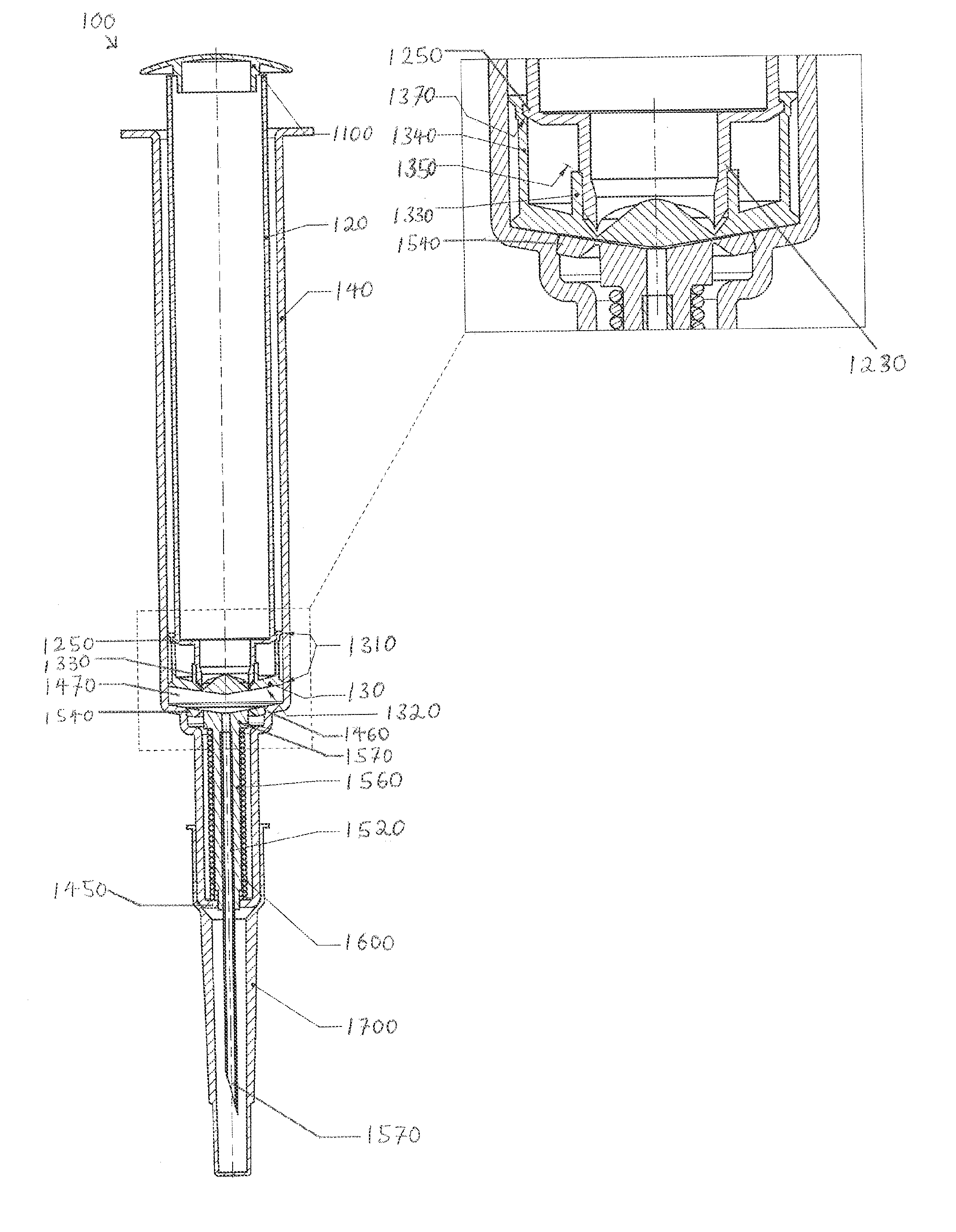
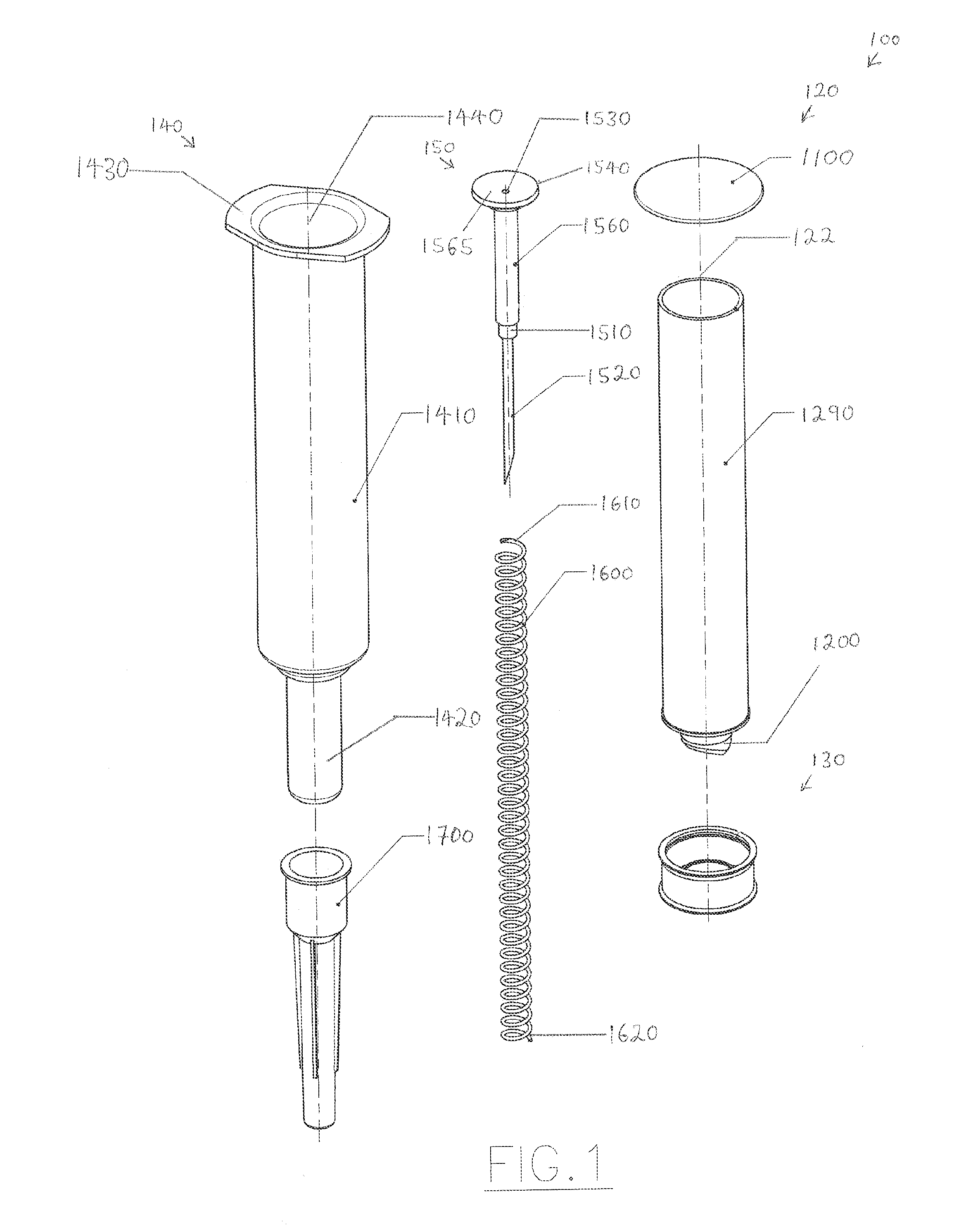
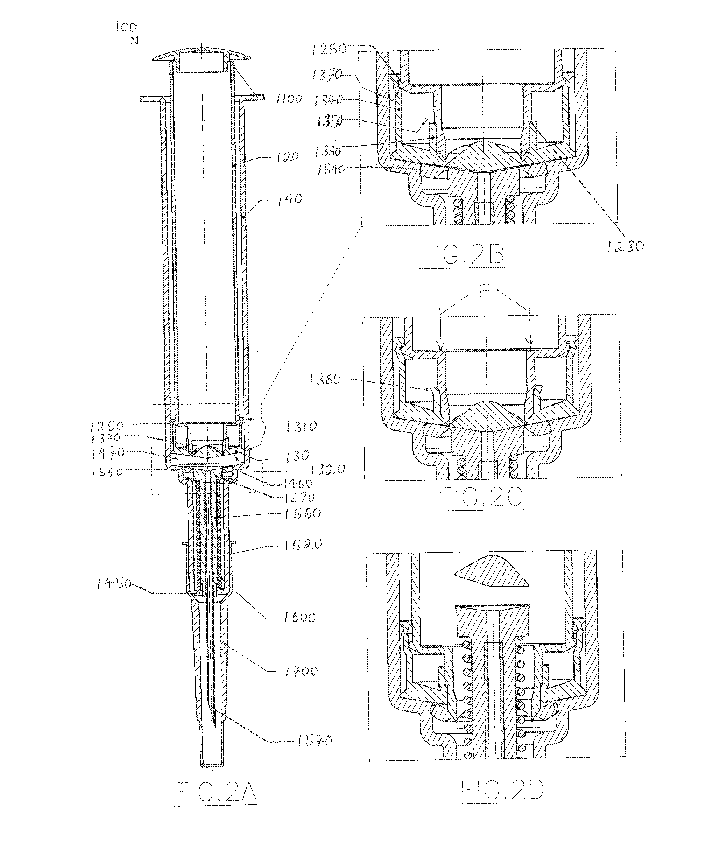
[0053]FIG. 1 is an exploded view of a syringe 100 according to the present invention. FIG. 2A is a cross-sectional view of the syringe of FIG. 1 when assembled. The parts of the syringe 100 are described next with reference to FIGS. 1 and 2A.

[0054]The syringe 100 comprises a hollow barrel 140 defining a chamber, a plunger 120 insertable within the chamber, a piston 130 which is inserted into the chamber before the plunger 120, and a retraction assembly 150 to be fitted at a front portion 1420 of the barrel 140. The barrel 140 functions as a housing providing support to the other parts of the syringe 100, e.g. the retraction assembly 150. In different versions of the embodiment, the size of the barrel 140 differs, so as to have varying fluid capacities. In these various versions of the embodiment, the barrel 140 has differing diameters, and the diameters of the piston 130, plunger 120 and / or retraction assembly 150 also differ to suit the diameter of the barrel 140. A spring 1600 sur...

third embodiment

[0092]We now turn to the invention, which is a needle assembly 200. The needle assembly 200 will be described with reference to FIGS. 5A to 5C. FIG. 5A is a needle assembly 200 in its initial state. FIG. 5B is a cross-sectional view of the needle assembly 200 of FIG. 5A when installed onto a syringe. FIG. 5C is a cross-sectional view of the needle assembly 200 of FIG. 5B but with a protector 1700 portion removed.

[0093]The needle assembly 200 comprises a needle hub 1510 with threads 520 on the outer side wall, a needle (cannula) 1520 extending from a first end 522 of the hub 1510 to a distal tip 1570, and a tubular neck 510 that is suitable for insertion into the needle holder 1560 of a syringe extending from a second end 524 of the hub. A cylindrical bore 515 runs continuously length-wise through the center of the needle 1520 from the tip 1570, and on through the center of the hub 1510, and further on through the center of the neck 510 before terminating as an opening 565 at an end ...


PUM


Abstract

A retractable syringe comprises a cutting head mounted on a plunger of the syringe. When the plunger is advanced to expel fluid from the syringe, the cutting crown cuts a retention mechanism which holds a needle unit of the syringe, allowing a drive mechanism to drive the needle unit into the syringe. The cutting crown is shaped to reduce the force which has to be applied to cut the retention mechanism. Furthermore, a disposable needle assembly for attachment to a syringe unit comprises a needle and connector element for connecting the needle to the syringe unit. The connector element encircles the needle and has a thread on its outer surface for mating with the syringe unit. When the needle assembly is mated with the syringe, a central bore of substantially constant bore extends from the tip of the needle into the interior chamber of the syringe.

Description

CROSS-REFERENCE TO RELATED APPLICATIONS[0001]This application is a filing under 35 U.S.C. 371 as the National Stage of International Application No. PCT / SG2010 / 000492, filed Dec. 31, 2010 and entitled “A Retractable Syringe with a Cutting Crown,” which claims the benefit of and priority to U.S. Provisional Patent Application No. 61 / 332,270, filed May 7, 2010 and entitled “Retractable Syringe with Self-Destruct Design” and U.S. Provisional Patent Application No. 61 / 373,926, filed Aug. 16, 2010 and entitled “Fittings for Syringe, Needles and Certain Other Medical Equipment, all of which are incorporated herein by reference in their entirety for all purposes.FIELD OF THE INVENTION[0002]The present invention relates to medical syringes. More particularly it relates to a retractable syringe, and to a disposable needle unit for attachment to a syringe unit to form a syringe assembly.BACKGROUND OF THE INVENTION[0003]Syringe assemblies having a needle (“cannula”) are commonly used for the d...

Claims


Application Information

Patent Timeline
Patent Type & Authority Patents(United States)
IPC IPC(8): A61M5/50A61M5/00A61M5/34A61M5/32
CPCA61M2205/586A61M5/5086A61M5/347A61M5/3234A61M5/508A61M5/3202
Inventor ANG, TEOH, HWA
Owner INTUITIVE CREATIONS PTE
Why Eureka
Try Eureka