Heat dissipation device with three-dimensional pulsation heat pipes

A technology of pulsating heat pipes and cooling devices, applied in indirect heat exchangers, lighting and heating equipment, etc., can solve problems affecting the performance of pulsating heat pipes, incomplete condensation in the condensation section, and dryness in the evaporation section, so as to avoid thermal resistance and start-up The effect of reducing power and improving heat transfer performance

Inactive Publication Date: 2019-11-15
UNIV OF SHANGHAI FOR SCI & TECH
View PDF11 Cites 2 Cited by
  • Summary
  • Abstract
  • Description
  • Claims
  • Application Information

AI Technical Summary

Problems solved by technology

[0004] However, most of the pulsating heat pipes currently used for electronic cooling are two-dimensional or flat-shaped pulsating heat pipes, which limits the relative positions of the heat source and the heat sink, and heat can only be transferred from one side of the heat pipe to the other; Secondly, there are a certain number of elbows in the evaporation section of most pulsating heat pipes. When the heating power increases to a certain level, it is easy to burn out and affect the performance of the pulsating heat pipe.
[0005] In addition, there are certain deficiencies in the traditional way of connecting the heat source of the heat pipe to the evaporation section. In the prior art, such as figure 1 The shown pulsating heat pipe is directly connected to a section of horizontal pipe from head to tail in order to realize closed-loop circulation and liquid filling, and the inlet and outlet are connected with a horizontal pipe and a one-way valve to form a closed loop
At the same time, incomplete condensation will also occur in the condensation section, which will cause the working fluid to return to the evaporation section and appear dry.

Method used


Image

  • Heat dissipation device with three-dimensional pulsation heat pipes
  • Heat dissipation device with three-dimensional pulsation heat pipes
  • Heat dissipation device with three-dimensional pulsation heat pipes

Examples


Embodiment

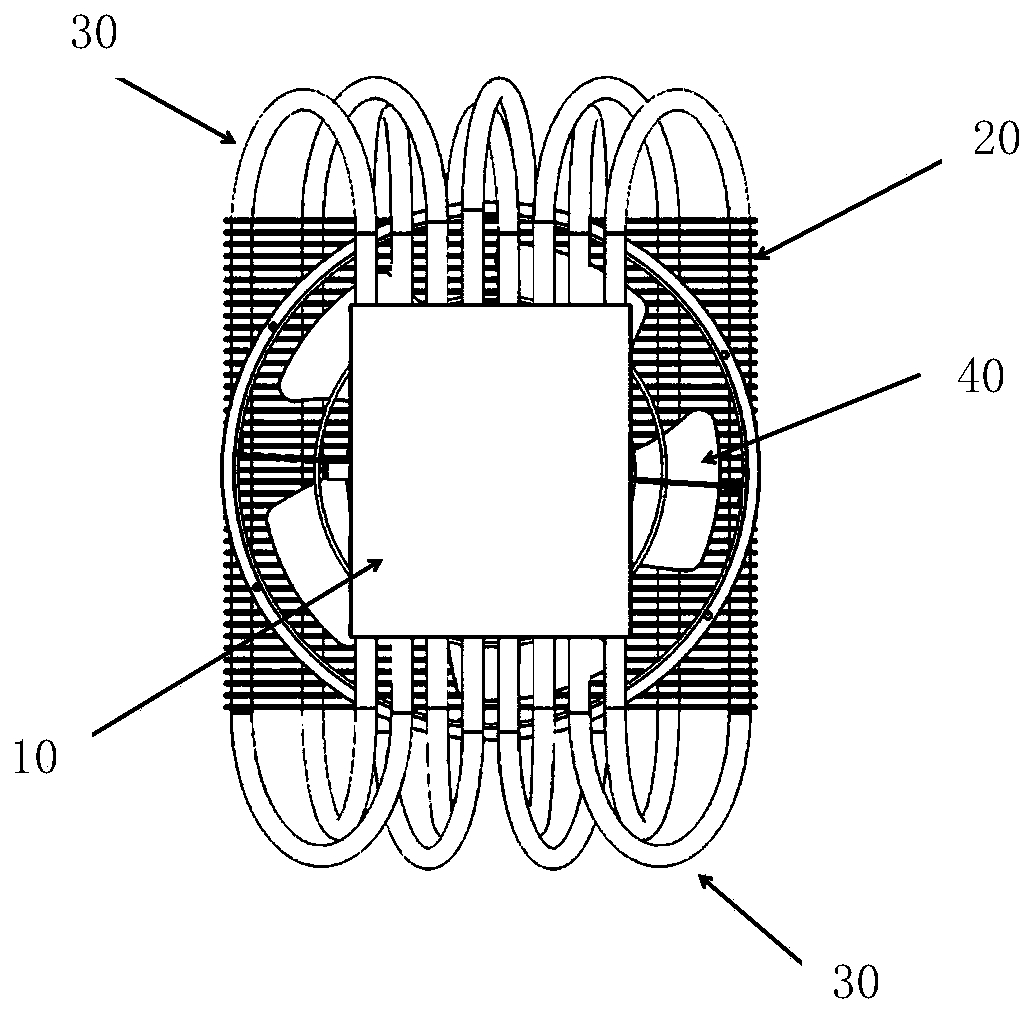
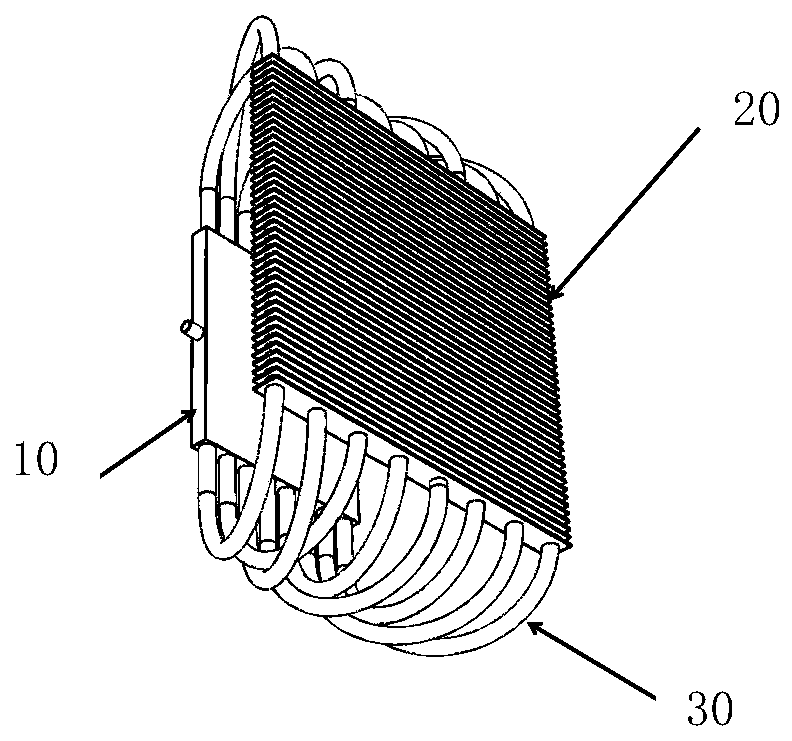
[0030] like figure 2 , image 3 As shown, the heat dissipation device with a three-dimensional pulsating heat pipe includes an evaporation unit 10 , a condensation unit 20 , an adiabatic unit 30 and a heat dissipation unit 40 .

[0031] like Figure 4 As shown, the evaporating unit 10 includes a plurality of evaporating pulsating heat pipes 11 arranged in a plane and an evaporating section 12 .

[0032] In the embodiment, the evaporating pulsating heat pipe 11 is made of red copper (or other materials) with good thermal conductivity and certain pressure bearing capacity.

[0033] The evaporating section 12 is planar. In the embodiment, the evaporating section 12 is made of a copper plate with good thermal conductivity, and a plurality of through holes are arranged in the thickness of the copper plate, and a plurality of evaporating pulsating heat pipes 11 pass through a plurality of through holes Set in copper plate. The liquid filling port 13 is placed on one side of the...


PUM


Abstract

The invention discloses a heat dissipation device with three-dimensional pulsation heat pipes. The heat dissipation device comprises an evaporation unit, a condensation unit, and a heat insulation unit, wherein a plurality of evaporation pulsation heat pipes and a plurality of condensation pulsation heat pipes are arranged in a plane; one end of each evaporation pulsation heat pipe communicates with one end of the corresponding condensation pulsation heat pipe through a first elbow, and the other end of each evaporation pulsation heat pipe communicates with the other end of the corresponding condensation pulsation heat pipe through a second elbow; and the plurality of evaporation pulsation heat pipes communicate with the plurality of condensation pulsation heat pipes through the pluralityof first elbows and the plurality of second elbows to form a closed-loop passage. According to the heat dissipation device with the three-dimensional pulsation heat pipes, on the basis of existing two-dimensional heat pipes, an evaporation section and a condensation section are arranged on two parallel planes which are parallel to each other, the evaporation section and the condensation section are connected through the elbows to form the closed loop, and the burning-dry phenomenon caused by excessive quantity of the elbows of a traditional heat pipe evaporation section is avoided; and a flat-plate structure can be well connected with a heat source, unnecessary heat resistance is avoided, and heat exchange performance is improved.

Description

technical field [0001] The invention belongs to the field of heat dissipation of electronic equipment, and in particular relates to a heat dissipation device with a three-dimensional pulsating heat pipe. Background technique [0002] The pulsating heat pipe (also known as the oscillating heat pipe) is a new type of heat pipe proposed by the Japanese scholar Akachi in the early 1990s. It can be formed by bending a capillary in a serpentine shape. It has a simple structure and does not require a liquid-absorbing core. As a typical representative of the new heat pipe technology in recent years, the pulsating heat pipe not only inherits the characteristics of the traditional heat pipe, such as simplicity, reliability, low price, and no power consumption, but also overcomes its limitations such as portability and boiling. The disadvantage of low thermal limit has the advantages of fast thermal response, outstanding heat transfer capacity and strong environmental adaptability. It ...

Claims


Application Information

Patent Timeline
Patent Type & Authority Applications(China)
IPC IPC(8): F28D15/04
CPCF28D15/04
Inventor 崔晓钰王鹏常志昊耿晖佘海龙
Owner UNIV OF SHANGHAI FOR SCI & TECH
Why Eureka
Try Eureka