Pulsating heat pipe with tilt-angle communicating pipe structure

A technology of pulsating heat pipes and connecting pipes, applied in indirect heat exchangers, lighting and heating equipment, etc., can solve problems such as affecting the normal operation and life of electronic components, difficulty in starting pulsating heat pipes, and reducing heat transfer characteristics, so as to avoid burning out. phenomenon, accelerated transfer, the effect of increasing the evaporation area

Inactive Publication Date: 2016-05-11
NANCHANG UNIV
View PDF7 Cites 3 Cited by
  • Summary
  • Abstract
  • Description
  • Claims
  • Application Information

AI Technical Summary

Problems solved by technology

[0004] Although the pulsating heat pipes in the prior art have the above-mentioned advantages, the disadvantages are that the pulsating heat pipes are difficult to start at lower loads, and are easy to dry out at higher loads.
These problems lead to ordinary pulsating heat pipes can only work normally in a small range, thereby reducing their heat transfer characteristics and affecting the normal work and life of electronic components

Method used


Image

  • Pulsating heat pipe with tilt-angle communicating pipe structure
  • Pulsating heat pipe with tilt-angle communicating pipe structure
  • Pulsating heat pipe with tilt-angle communicating pipe structure

Examples


Embodiment Construction

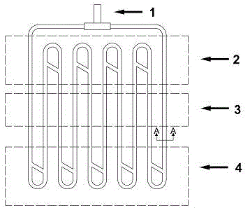
[0029] The pulsating heat pipe of the present invention includes a vacuum pumping / injecting working fluid section, an evaporation section with an oblique connecting pipe, an adiabatic section and a condensation section with an oblique connecting pipe;

[0030] The pulsating heat pipe is a closed-loop pulsating heat pipe;

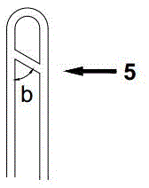
[0031] The evaporating section with oblique connecting pipe connects a connecting pipe with an angle to the straight pipe at the U-bend straight pipe of the traditional evaporating section to connect two adjacent straight pipes in the evaporation section;

[0032] The condensing section with oblique connecting pipe connects a connecting pipe with an angle to the straight pipe at the U-bend straight pipe of the traditional condensing section to connect two adjacent straight pipes in the condensing section;

[0033] The adiabatic section has the same pipe diameter as the evaporation section and the condensation section and is integrally formed;

[0034] The vacuum pumpi...


PUM


Abstract

The invention discloses a pulsating heat pipe with a tilt-angle communicating pipe structure. The pulsating heat pipe structurally comprises a vacuum-pumping/medium-injecting section, an evaporating section with an inclined communicating pipe, a heat insulating section and a condensing section with the inclined communicating pipe, wherein the inclined communicating pipe is additionally arranged on the traditional evaporating section for communicating two adjacent straight pipes in the evaporating section. One part of evaporated gas enters the inclined communicating pipe while passing through the inclined communicating pipe, so that transfer of evaporated gas to the condensing section is quickened to avoid a dry-out phenomenon. Meanwhile, due to the inclined communicating pipe, the evaporation area is increased, so that the pulsating heat pipe is easier to start. The inclined communicating pipe is additionally arranged on the conventional condensing section for communicating two adjacent straight pipes in the condensing section. One part of the condensed medium flows into the inclined communicating pipe while passing through the inclined communicating pipe, so that the condensed medium enters next-round condensation to the evaporating section quicker; in the evaporating section and the condensing section, an included angle between the inclined communicating pipe and a main channel thereof can be the same and also can different, so that the heat transfer property of the pulsating heat pipe is reinforced, and the start-up time of the pulsating heat pipe is shortened.

Description

Technical field [0001] The invention relates to a pulsating heat pipe with a connected pipe with an inclination angle, which belongs to the field of electronic device cooling and high-efficiency heat transfer. Background technique [0002] With the rapid development of the electronics industry, the performance of electronic devices is getting better and better, and the degree of integration is getting higher and higher, and the power per unit area of ​​the electronic components is correspondingly larger and larger. At the end of the 1990s, the heat flux density that the computer mainframe chip can generate has reached 100W / cm 2 . For the small internal space of electronic devices, such a high heat flux density will cause the electronic devices to generate local or overall high temperature, which will reduce the performance of the electronic equipment at a minimum, and cause thermal deformation, causing fatigue damage or failure of the electronic components. According to statisti...

Claims


Application Information

Patent Timeline
Patent Type & Authority Applications(China)
IPC IPC(8): F28D15/04
CPCF28D15/04
Inventor 张莹王志强
Owner NANCHANG UNIV
Why Eureka
Try Eureka