Steam sterilizer

a sterilizer and steam technology, applied in the field of sterilizers, can solve the problems of reducing the likelihood of heat loss to the surrounding environment, affecting the sterilization effect of items in the steam sterilizer, and affecting the sterilization effect of the surrounding environment, so as to reduce the likelihood of heat loss

Active Publication Date: 2014-10-21
AMERICAN STERILIZER CO
View PDF16 Cites 10 Cited by
  • Summary
  • Abstract
  • Description
  • Claims
  • Application Information

AI Technical Summary

Benefits of technology

[0008]An advantage of the present invention is a steam sterilizer for sterilizing medical items and the like.
[0009]Another advantage of the present invention is a steam sterilizer having a cavity surrounding a chamber of the steam sterilizer.
[0010]Another advantage of the present invention is a steam sterilizer as described above having a heating element disposed within the cavity.
[0011]Another advantage of the present invention is a steam sterilizer as described above wherein water is vaporized within the cavity surrounding the chamber of the steam sterilizer.
[0012]Another advantage of the present invention is a steam sterilizer as described above that reduces the likelihood of heat loss to the surrounding environment during critical phases of a steam sterilization cycle.
[0013]These and other advantages will become apparent from the following description of a preferred embodiment taken together with the accompanying drawings and the appended claims.

Problems solved by technology

If the temperature of the steam in the chamber falls below the predetermined temperature range(s), the items in the steam sterilizer may not be properly sterilized.
However, even the best insulation will allow some heat to be lost to the surrounding environment.
Heat loss from the boiler and from the plurality of conduits increases the risk that the temperature in the chamber of the sterilizer will fall below the predetermined temperature range(s) during critical phases of the steam sterilization cycle.

Method used


Image

  • Steam sterilizer
  • Steam sterilizer
  • Steam sterilizer

Examples


Embodiment Construction

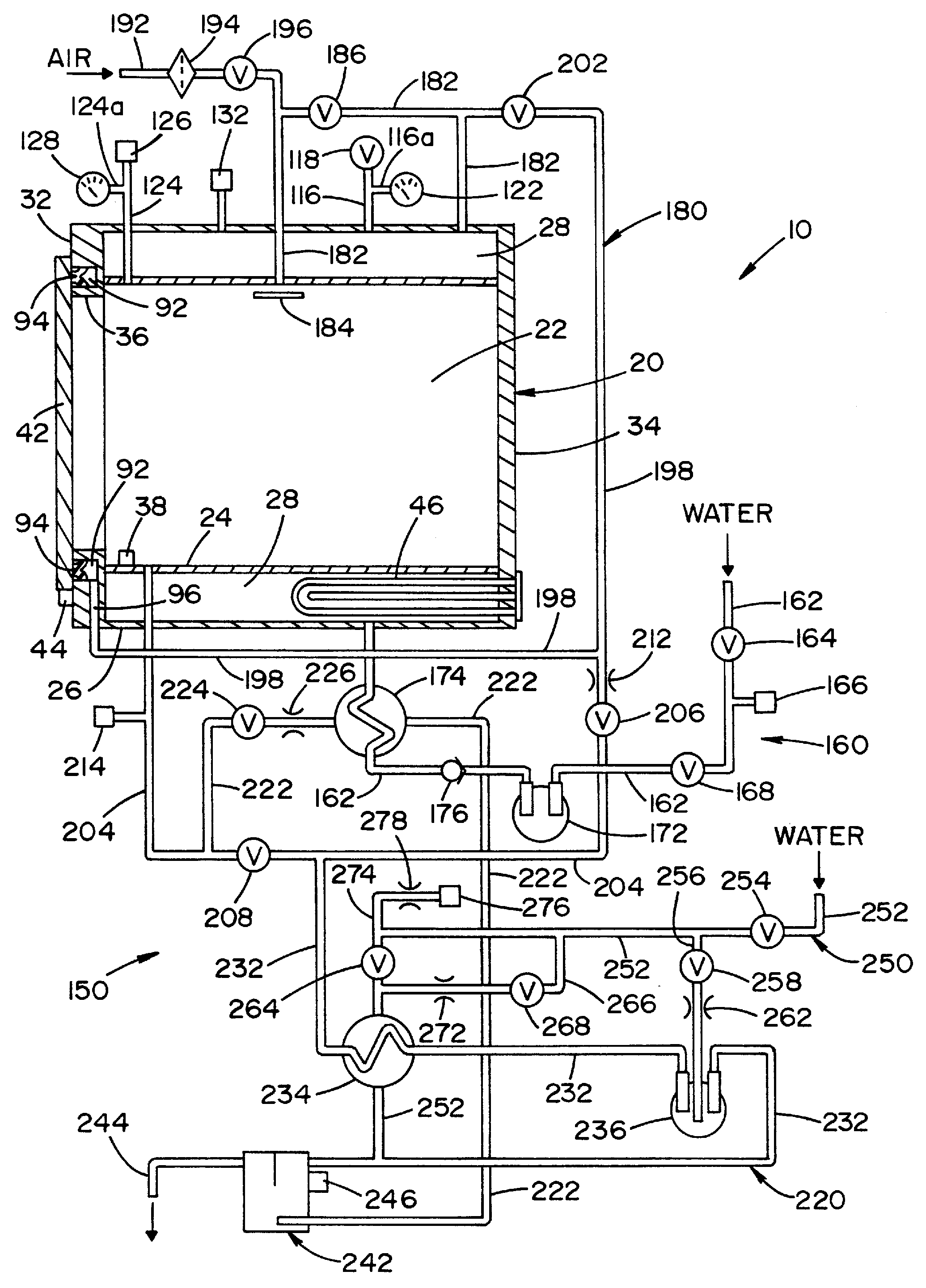
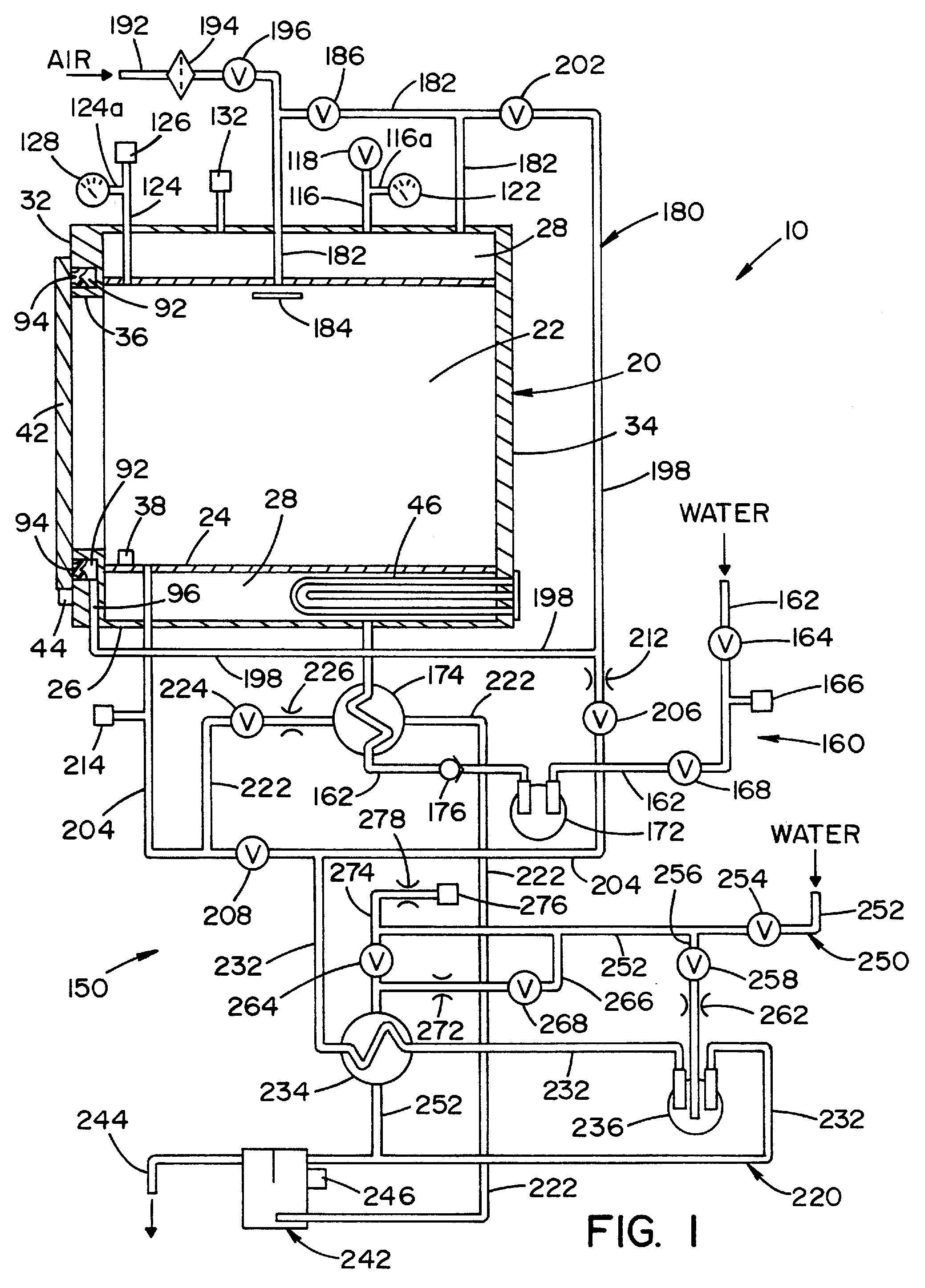
[0018]Referring now to the drawings wherein the showings are for the purpose of illustrating a preferred embodiment of the invention only and not for the purpose of limiting same, FIG. 1 shows a schematic view of steam sterilizer 10 for sterilizing medical instruments and other items.

[0019]Sterilizer 10 includes a controller 12, schematically illustrated in FIG. 3, for controlling the operation of sterilizer 10. It is contemplated that sterilizer 10 may be designed and configured to rest upon a table or countertop or to be mounted into a self-supporting frame.

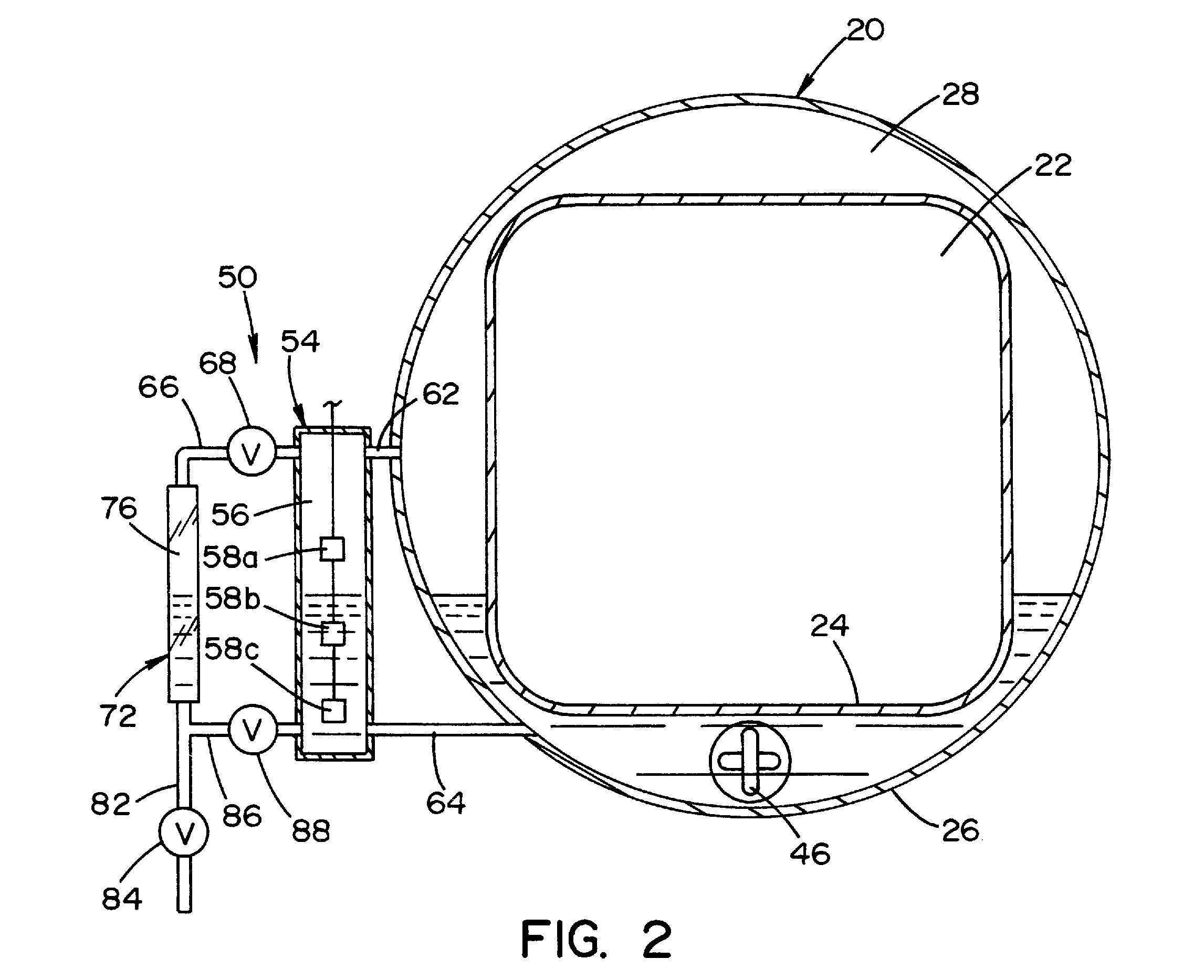
[0020]As shown in FIG. 1, sterilizer 10 is basically comprised of a vessel 20 and a fluid circuit 150. Vessel 20 includes an inner wall 24, an outer wall 26, a first end plate 32 and a second end plate 34. First end plate 32 is attached to one end of inner wall 24 and outer wall 26. Second end plate 34 is attached to another end of inner wall 24 and outer wall 26. Inner wall 24, first end plate 32 and second end plate 34 define...


PUM

PropertyMeasurementUnit
temperatureaaaaaaaaaa
pressureaaaaaaaaaa
temperatureaaaaaaaaaa

Abstract

A sterilizer for sterilizing instruments and devices disposed therein. The sterilizer includes a vessel that has an inner wall and an outer wall. The inner wall defines a sterilization chamber. The outer wall is spaced from the inner wall to define a cavity surrounding the sterilization chamber. A heating element for vaporizing a fluid is disposed in a lower portion of the cavity. A fluid circuit is fluidly connected to the vessel to convey fluid to the cavity, to convey steam from the cavity to the sterilization chamber and to exhaust steam from the sterilization chamber. The fluid circuit includes a conduit that fluidly connects the sterilization chamber to the cavity. A valve is disposed in the conduit for controlling the flow of steam from the cavity to the sterilization chamber. A boiler pump is provided for conveying fluid to the cavity of the vessel.

Description

FIELD OF THE INVENTION[0001]The present invention relates generally to sterilizers and, more particularly, to a steam sterilizer for medical, dental, and surgical equipment and will be discussed with particular reference thereto.BACKGROUND OF THE INVENTION[0002]Steam sterilizers are widely used in hospitals, laboratories, and other facilities to sterilize many types of items. A typical steam sterilizer includes a chamber to receive the items to be sterilized and a steam jacket that surrounds the chamber. The steam sterilizer exposes the items in the chamber to heated steam during a steam sterilization cycle.[0003]The temperature and pressure of the steam must meet specific requirements during critical phases of the steam sterilization cycle in order for the items to be sterilized. In particular, the steam in the chamber must be maintained within a predetermined temperature range(s) during critical phases of the steam sterilization cycle. If the temperature of the steam in the chambe...

Claims


Application Information

Patent Timeline
Patent Type & Authority Patents(United States)
IPC IPC(8): A61L2/07A61L2/00
CPCA61L2/07A61L2202/24A61L2202/11A61L2202/122
Inventor BUCZYNSKI, PETER, J.
Owner AMERICAN STERILIZER CO
Why Eureka
Try Eureka