
Method of and architecture for a virtual wireless network

a wireless network and wireless network technology, applied in the field of virtual wireless networks, can solve the problem of limiting the web servers the user is actually allowed to access, and achieve the effect of expanding operations

Active Publication Date: 2014-10-21
SHOO 533 +1
View PDF10 Cites 2 Cited by
  • Summary
  • Abstract
  • Description
  • Claims
  • Application Information

AI Technical Summary

Benefits of technology

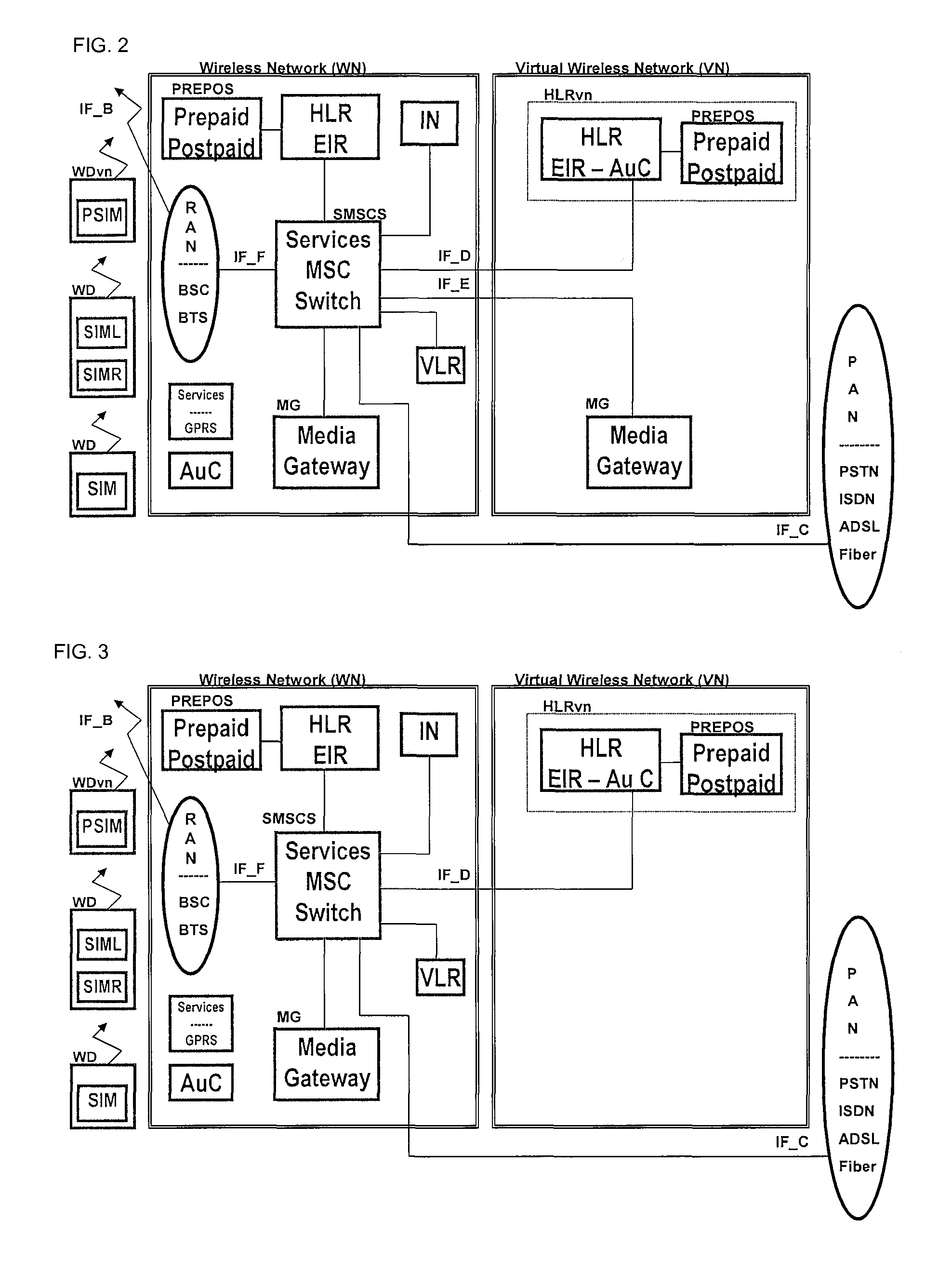
[0016]Where the subscriber operates a wireless device with two or more IMSIs, then the apparatus can be operable to manage remotely the selection of an appropriate IMSI on the device, for example based lowest cost call routing or on features available when one particular IMSI is used and not another. The home location register itself may manage the remote selection of an appropriate IMSI on the device.
[0042]An implementation of the invention gives each wireless device user the freedom to choose the cheapest option for each call set-up route for any outgoing traffic (such as outgoing SMS, voice calls, data calls) and would thus allow virtual wireless networks to expand operations by entering a least two commercial agreements with wireless network operators in the same country or in two or more different countries. It would also allow a virtual wireless network operator to attract wireless device users in its home country and also in any country with whom any associated wireless network operators have a roaming agreement with.

Problems solved by technology

The restrictions can even limit which web servers the user is actually allowed to access; in most or all cases the restrictions will limit the users in their home country to only one wireless network, i.e. the home wireless network to which the user is subscribed to or its associated virtual wireless network.
With existing systems however, this is very difficult because mobile network operators have little economic incentive to provide end-users with the freedom to choose the cheapest network for each call set-up route for any outgoing traffic, such as outgoing-SMS, -voice call, -data call.
In fact, they have every economic incentive to make this very difficult.
The ownership and control that a network operator has over its HLR constitutes a major entry barrier to competitors, especially virtual wireless network operators, seeking to offer lower cost services,

Method used


Image

  • Method of and architecture for a virtual wireless network
  • Method of and architecture for a virtual wireless network
  • Method of and architecture for a virtual wireless network

Examples


Embodiment Construction

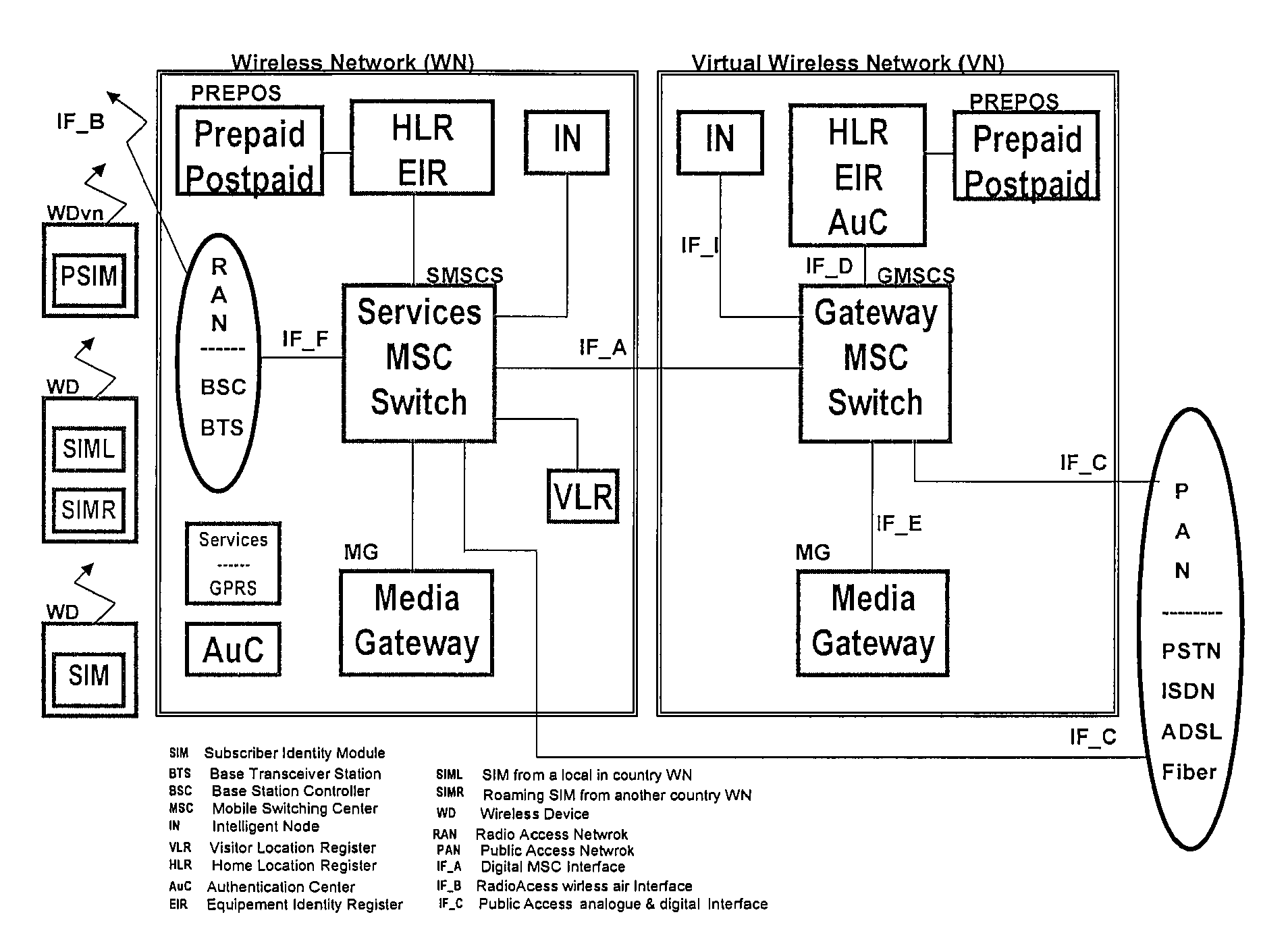
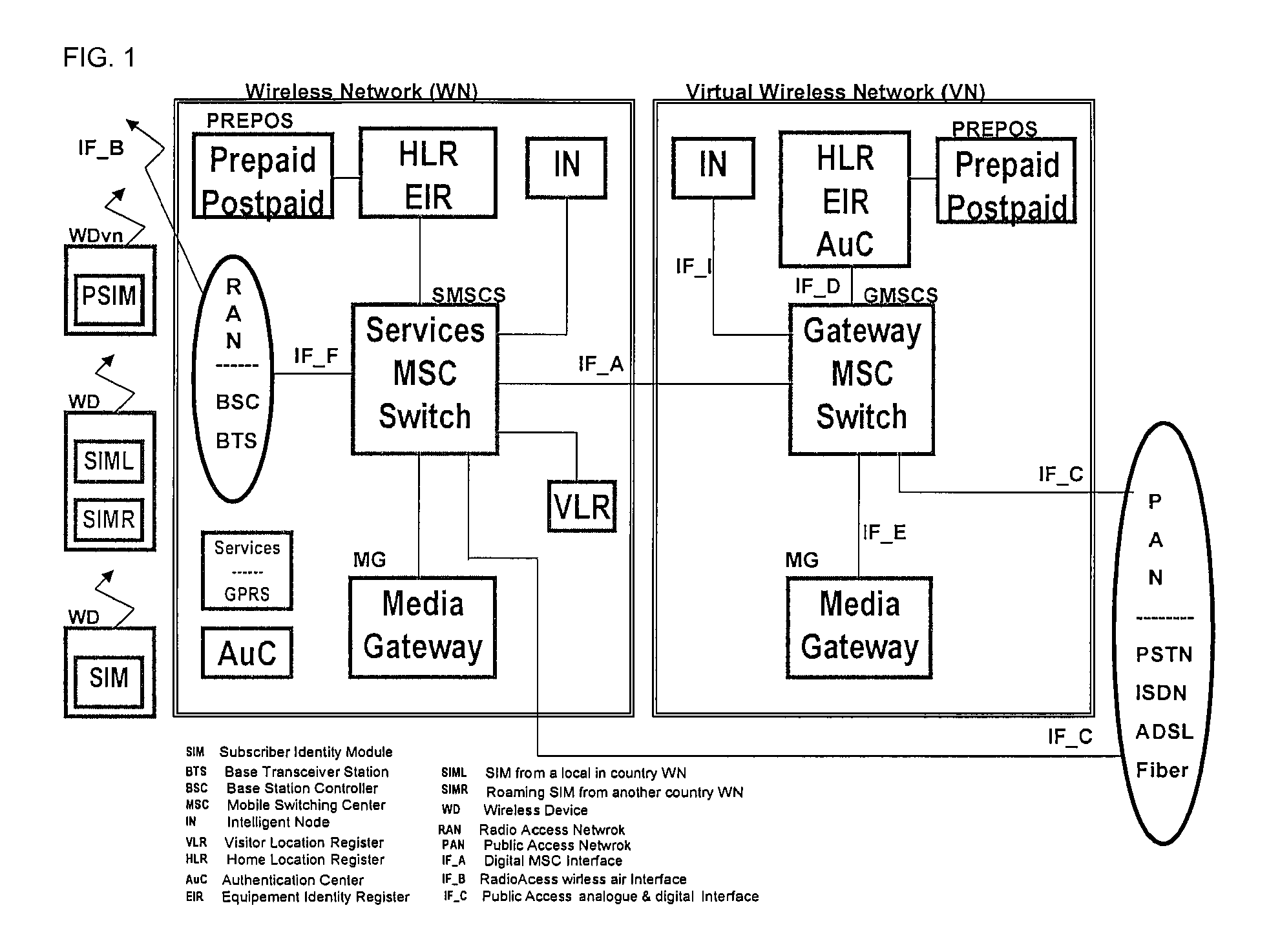
[0052]Specifically, FIG. 1 is a block diagram of a wireless communications system, which can be used to implement an embodiment of the present invention. For this exemplary embodiment, there is shown a wireless device (WD), yet another wireless device (WDvn) with a built-in PSIM, a wireless network (WN) and a Virtual Wireless Network (VN), interconnected between each other.

[0053]Voice and data communication between the WD and the wireless network is through the wireless interface IF-B, which in turn allows connection to any communication device connected, by wire or wirelessly, to the wireless network. The entire system can therefore include, but is not limited to, a fixed network, an application server, a media server, a voice over IP network or even a different wireless network, or a multiple configuration of the previous; multiple wireless devices (WDvn), multiple wireless interfaces (IF-Bn), multiple wireless networks (WNn), multiple fixed networks through the public access netw...


PUM


Abstract

A virtual wireless network including a server running a home location register (HLR), the home location register being associated solely with a virtual wireless network operator that does not have any licensed frequency spectrum, but provides wireless services to a subscriber by using the wireless basestations of a wireless network operator that does have licensed frequency spectrum.

Description

CROSS REFERENCE TO RELATED APPLICATIONS[0001]This application claims the priority of PCT / GB2007 / 000929 filed on Mar. 16, 2007, which claims priority to GB 0605283, filed Mar. 16, 2006, the entire contents of which are hereby incorporated herein by reference.FIELD OF THE INVENTION[0002]This invention relates in general terms to virtual wireless networks. It relates in particular to a method of, and architectures for, virtual wireless networks interfacing and interconnecting with wireless networks and public access networks. In- and out-going, voice and data calls can be handled. It relates also to interfacing and connecting wireless devices to both virtual and non-virtual wireless networks for in- and out-going SMS, voice and data call routing.BACKGROUND OF THE INVENTION[0003]Wireless devices can now handle voice and / or data, allowing simplex and / or duplex voice calls, video calls, text messaging, internet browsing. Some wireless communication devices can now also handle voice-over-i...

Claims


Application Information

Patent Timeline
Patent Type & Authority Patents(United States)
IPC IPC(8): H04W8/04H04W4/00H04W8/26
CPCH04W8/26H04W8/04H04M1/026H04Q3/0062
Inventor CAMILLERI, MICHAELMERINO GONZALEZ, JOSE LUIS
Owner SHOO 533
Learn More