Mechanical locking of floor panels

a technology of floor panels and locking mechanisms, applied in the direction of mechanical equipment, walls, building repairs, etc., can solve the problems of high separation force, inability to connect floor panels, and inability to prevent separation

Active Publication Date: 2014-10-28
VÄLINGE INNOVATION AB
View PDF478 Cites 94 Cited by
  • Summary
  • Abstract
  • Description
  • Claims
  • Application Information

AI Technical Summary

Benefits of technology

[0025]The present invention aims at a set of building panels, especially floor panels or a floating flooring with a mechanical locking system comprising a separate displaceable tongue on the short edge which is configured to improve installation and disconnection of floor panel installed with vertical folding or angling and which will counteract or prevent separation of the short edges during installation.
[0026]The invention is based on a first basic understanding that such separation problems are related to the separate displaceable tongue in a folding lock, which has to be pressed inwardly into the displacement groove in order to snap back horizontally towards the tongue groove during the vertical folding. The objective of the invention is to provide a locking system that could be locked with vertical motion or angling of an adjacent edge and where the separation force of the displaceable tongue during vertical motion or angling is reduced considerably or preferably eliminated due to the fact that the inwardly directed displacement of the displaceable tongue into the displacement groove during installation is reduced considerably or completely eliminated.

Problems solved by technology

The inventor has analysed several types of floor panels and discovered that there is a considerable risk that the short edges could be pushed away from each other during installation and that a gap could occur between the edge portions of the short edges.
Such a gap could prevent further installation and the floor panels will not be possible to connect.
It could also cause serious damage to the locking system at the short edges.
Such an installation method is however complicated and difficult to use since three actions have to be combined and used simultaneously in connection with angling down of the long edges as described below.
The inventor has discovered that separation and installation problems often occur when the panels have a small thickness and small compact locking systems on the long edges or when the panel core is made of a material with smooth surfaces such as high density fibreboard (HDF).
Such problems could also occur when the panels are short or in connection with the installation of the first or last panel in each row since such installation is generally made with panels which are cut to a smaller length in order to adapt the floor to the wall position.
Separation problems are of course extremely difficult to handle in any type of panels using locking systems with a strong flexible tongue that creates a substantial horizontal separation pressure during the vertical folding.
Such strong tongues are very important in many applications where a high quality vertical connection is required and panels with such flexible tongues are very difficult to install with the known installation methods.
This creates a resistance, which is a disadvantage during installation.
A locking system adapted to lock thin laminate floorings of 5-8 mm with a core of HDF is not always possible to use to lock for example thick wood floorings with a thickness of 14-25 mm and with a core of various types of wood spices and qualities.

Method used


Image

  • Mechanical locking of floor panels
  • Mechanical locking of floor panels
  • Mechanical locking of floor panels

Examples


Embodiment Construction

[0090]FIGS. 1-4 and the related description below describe published embodiments and are used to explain the major principles of the invention. The showed embodiments are only examples.

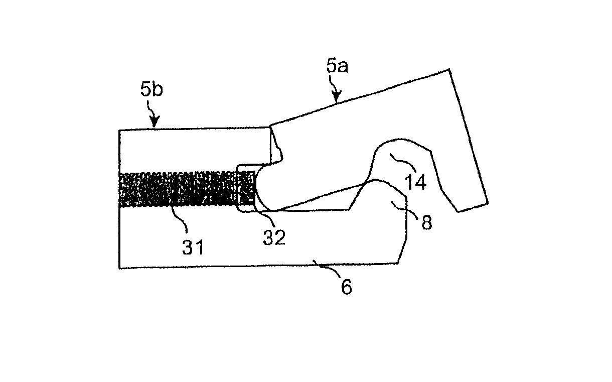
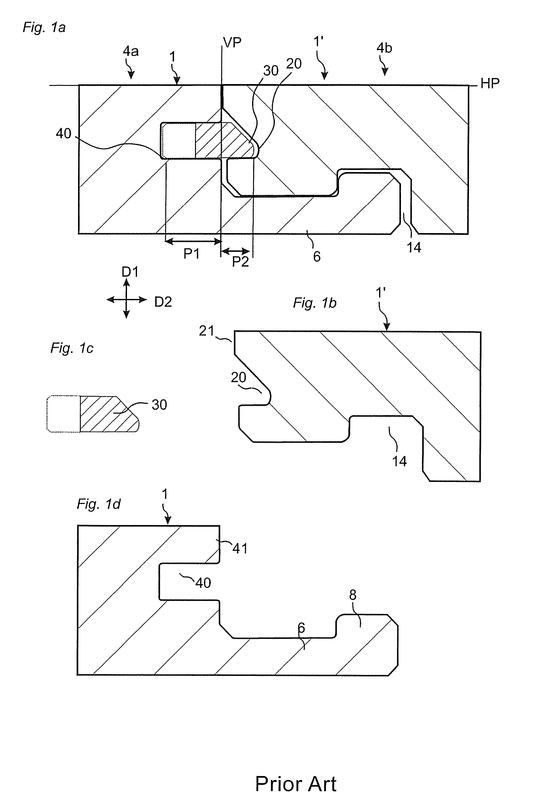
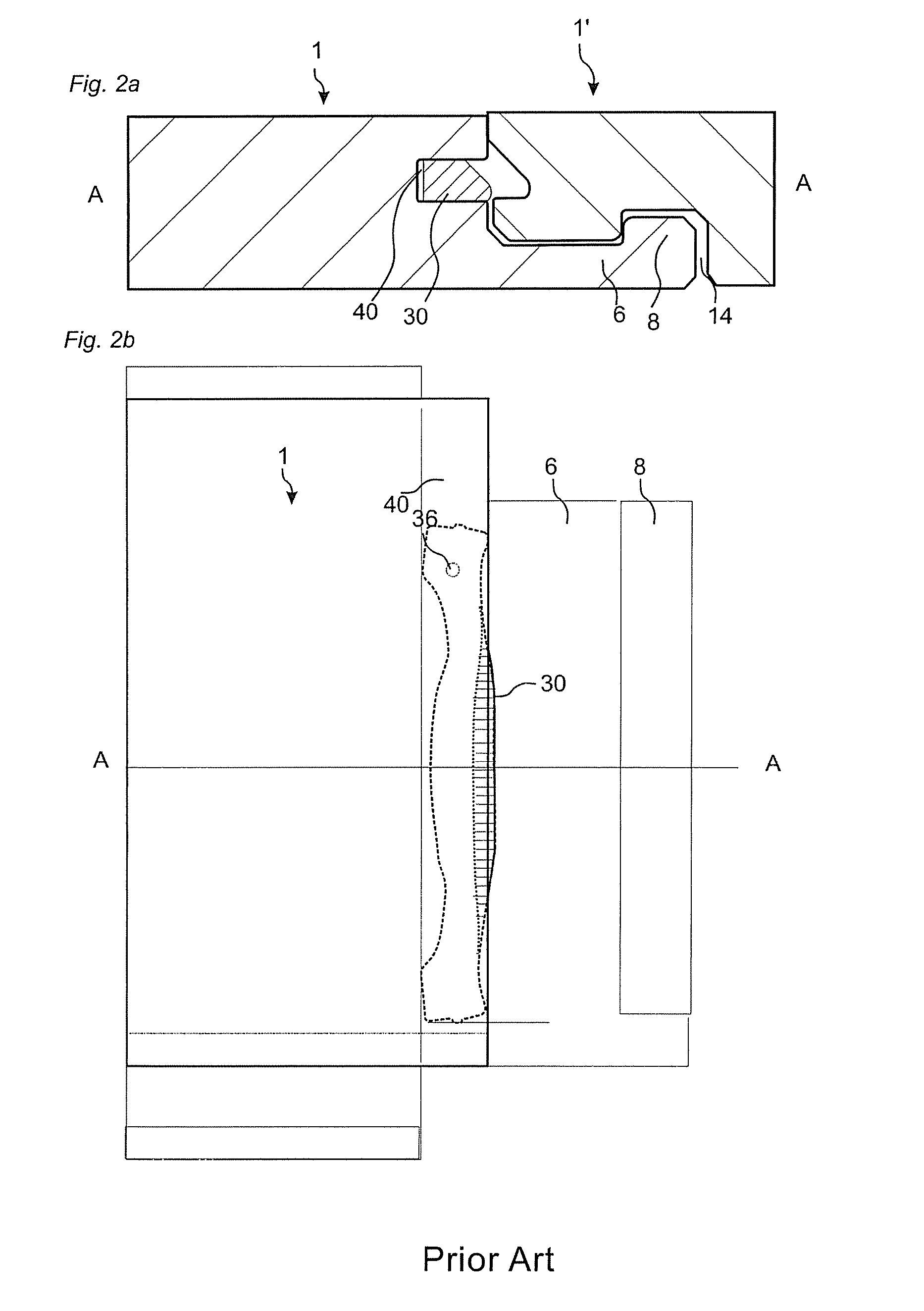
[0091]A prior art floor panel 1, 1′ provided with a mechanical locking system and a flexible tongue 30 is described with reference to FIGS. 1a-1d.

[0092]FIG. 1a illustrates schematically a cross-section of a joint between a short edge joint edge 4a of a panel 1 and an opposite short edge joint edge 4b of a second panel 1′.

[0093]The front faces of the panels are essentially positioned in a common horizontal plane HP, and the upper parts 21, 41 of the joint edges 4a, 4b abut against each other in a vertical plane VP. The mechanical locking system provides locking of the panels relative to each other in the vertical direction D1 as well as the horizontal direction D2.

[0094]To provide joining of the two joint edges in the D1 and D2 directions, the edges of the floor panel have in a manner known per se a l...


PUM

PropertyMeasurementUnit
anglesaaaaaaaaaa
thicknessaaaaaaaaaa
thicknessaaaaaaaaaa

Abstract

Floor panels (1, 1′) are shown, which are provided with a mechanical locking system on long (5a, 5b) and short edges (4a, 4b) allowing installation with angling of long edges and where the short edge locking system has a displaceable tongue that is displaceable essentially in one direction from an inner unlocked position to an final locked position.

Description

CROSS-REFERENCE TO RELATED APPLICATIONS[0001]The present application is a continuation-in-part of PCT / SE2007 / 000836, claims the benefit of U.S. Provisional Patent Application No. 60 / 869,181, filed on Dec. 8, 2006; and claims priority of SE 0602645-4, filed on Dec. 8, 2006. The entire contents of these applications are incorporated herein by reference.AREA OF INVENTION[0002]The invention generally relates to the field of floor panels with mechanical locking systems comprising a separate flexible tongue allowing easy installation. The invention provides new improved locking systems and installation methods for building panels, especially floor panels.BACKGROUND OF THE INVENTION[0003]In particular, yet not restrictive manner, the invention concerns a mechanical locking system for rectangular floor panels with long and short edges. It should be emphasized that long and short edges are only used to simplify the description. The panels could also be square, they could have more than 4 edg...

Claims


Application Information

Patent Timeline
Patent Type & Authority Patents(United States)
IPC IPC(8): E04B5/00E04F15/00
CPCE04F2201/0138E04F2201/0115E04F2201/0588E04F2201/0146E04F2201/0552E04F2201/0176E04F2201/0169E04F2201/0153E04F15/02E04F2201/0547F16B5/008E04F2201/0541E04B5/00E04B1/38E04C2/38E04F15/02038E04F15/04E04F15/02005E04F2201/05
Inventor PERVAN, DARKO
Owner VÄLINGE INNOVATION AB
Why Eureka
Try Eureka