
Dual valve

Active Publication Date: 2014-10-28
BURNER SYST INT
View PDF9 Cites 7 Cited by
  • Summary
  • Abstract
  • Description
  • Claims
  • Application Information

AI Technical Summary

Benefits of technology

The present invention aims to provide an improved dual valve construction that takes advantage of production efficiencies achieved with single valve constructions. The technical effects of the invention are increased production efficiency and improved performance of the dual valve construction.

Problems solved by technology

However, this configuration would require the operator to manipulate the two valves independently which might be cumbersome or lead to confusion.
Unfortunately, the production of this type of valve requires a significant investment in manufacturing equipment since this type of valve cannot normally be produced on the same equipment as the single valves that have been produced for years.
This low volume means that the production efficiencies achieved for the single valve are generally not normally achievable for the dual outlet valve.

Method used


Image

  • Dual valve
  • Dual valve
  • Dual valve

Examples


Embodiment Construction

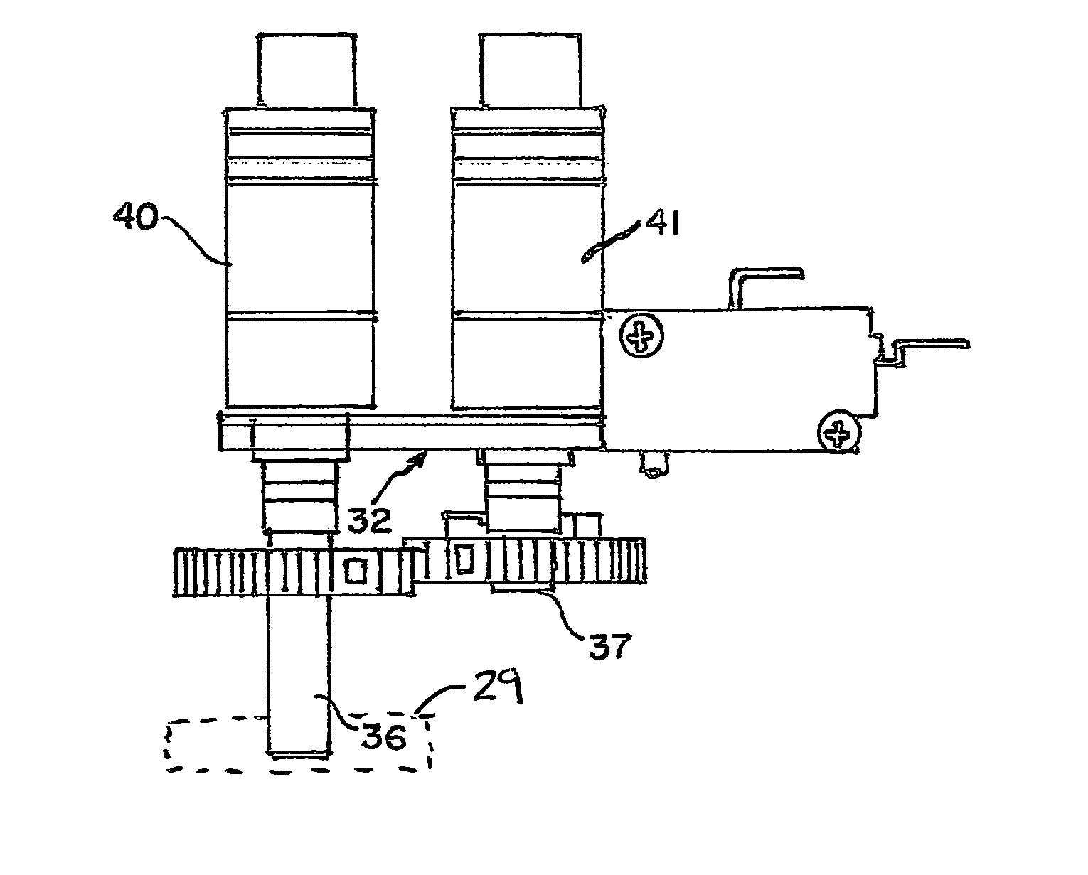
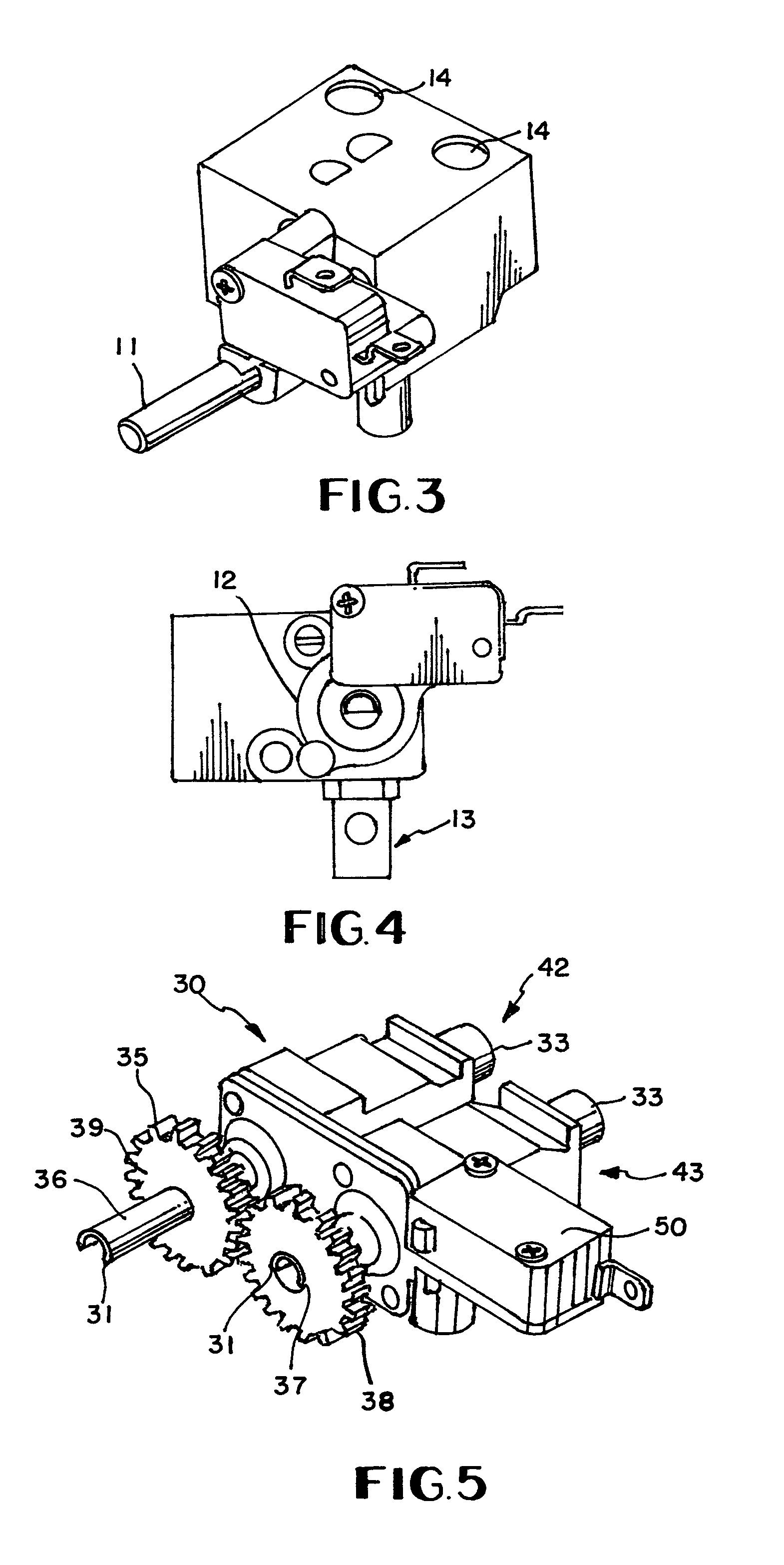
[0022]FIG. 5 shows the dual valve 30 construction in accordance with a presently preferred embodiment of the present invention. Specifically, dual valve 30 has a dual control system 31 which includes a first control stem 36 for use with operably first valve portion which preferably connects to operating knob (not shown). A second control stem 37 may be shorter than the first shortened control stem 36. Second control stem 37 is preferably long enough to connect to second gear 38 which cooperates with first gear 39 (connected to first control stem 36) as will be explained in detail below.

[0023]The first control stem 36 preferably extends from a first valve portion 40 while second control stem 37 extends from the second valve portion 41. The first and second valve portions 40,41 preferably are connected with or joined with and / or share a single face plate 32 which not only joins the first and second valve portions 40,41, but also preferably connects the first and second valve portions ...


PUM


Abstract

A dual valve construction partners first and second valve portions with a mechanical linkage such as gears to operably couple the control stems together. The gears need not be identical and in fact a first gear may have flats so that motion of the first gear need not always move the second gear proportionally. Furthermore, the gears may have differing gear ratios at different portion of the gears.

Description

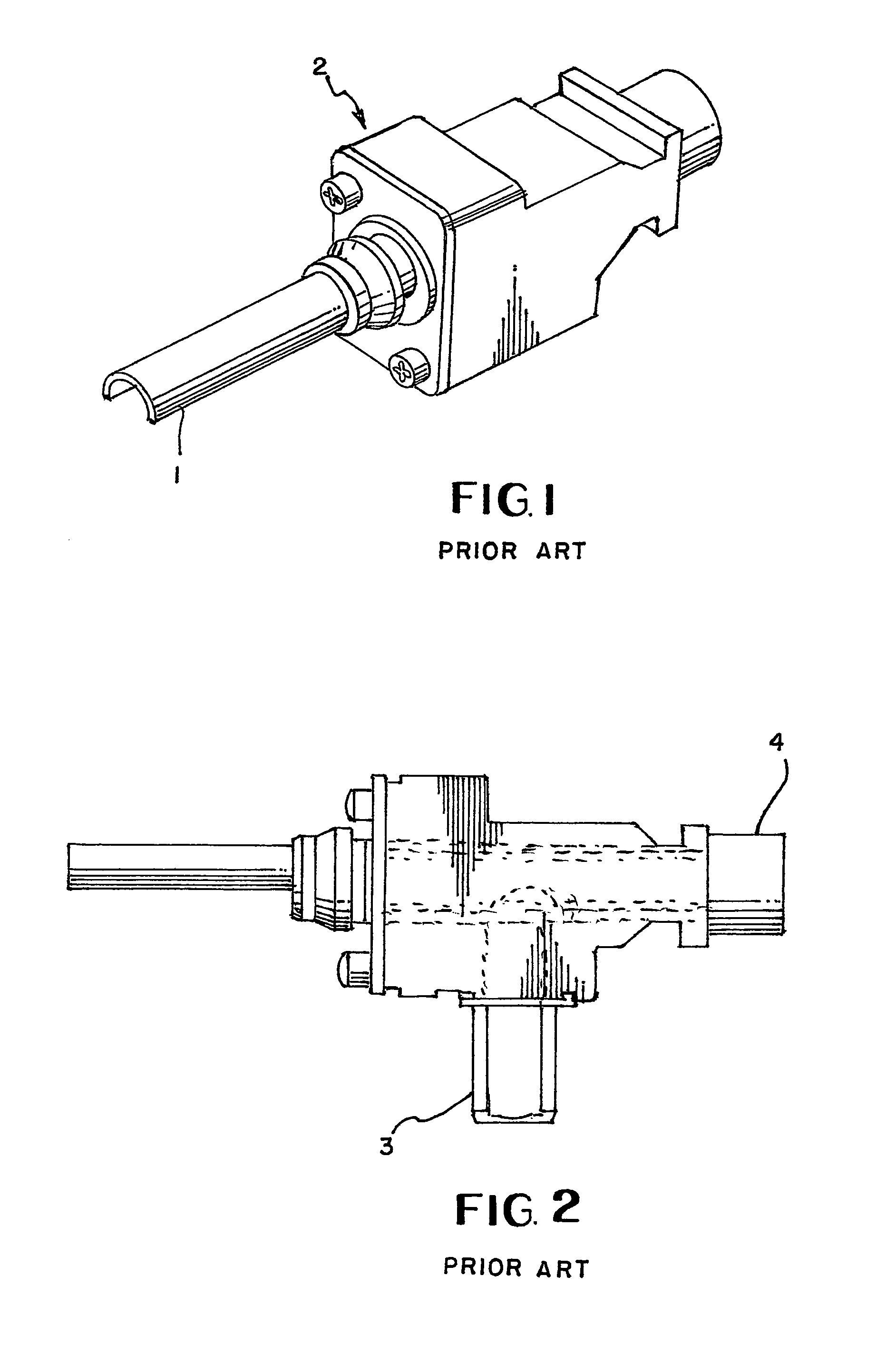
CLAIM OF PRIORITY[0001]This application claims the benefit of U.S. Provisional Patent Application No. 61 / 625,406 filed Apr. 17, 2012 which is incorporated in its entirety by reference.FIELD OF THE INVENTION[0002]The present invention relates to a dual valve constructed from operably coupled single valves.DESCRIPTION OF RELATED ART[0003]Gas component suppliers such as BSI have invested many millions of dollars over the years for manufacturing and assembly equipment to produce top burner gas valves for gas cooking appliances similar to what is shown in FIGS. 1 and 2. This type of valve is used to control and meter the amount of gas delivered to a single burner. The annual global production of these types of valves is in excess of 40 million. Obviously, with this type of annual volume vendors such as BSI have invested money to optimize production efficiencies and reduce costs. Some of the design features of this type of valve shown in the figures include: (1) a single control stem, (2)...

Claims


Application Information

Patent Timeline
IPC IPC(8): F16K31/53F16K5/00F23K5/00
CPCF23K5/007F23N2035/24F23N1/007Y10T137/87877Y10T137/87096Y10T137/87732F23N2035/18F23N2235/18F23N2235/24
Inventor SAPP, STEPHENFROST, TIMOTHY
Owner BURNER SYST INT
Learn More