Method, apparatus, and arrangement for a lifeline system

a lifeline and apparatus technology, applied in safety belts, rope railways, ways, etc., can solve the problems of workers not being able the most dangerous aspect of working at high heights above the ground, and the need for workers to pass each other, etc., to achieve the effect of increasing safety and being easy to implement and utiliz

Active Publication Date: 2014-10-28
MSA TECH
View PDF19 Cites 3 Cited by
  • Summary
  • Abstract
  • Description
  • Claims
  • Application Information

AI Technical Summary

Benefits of technology

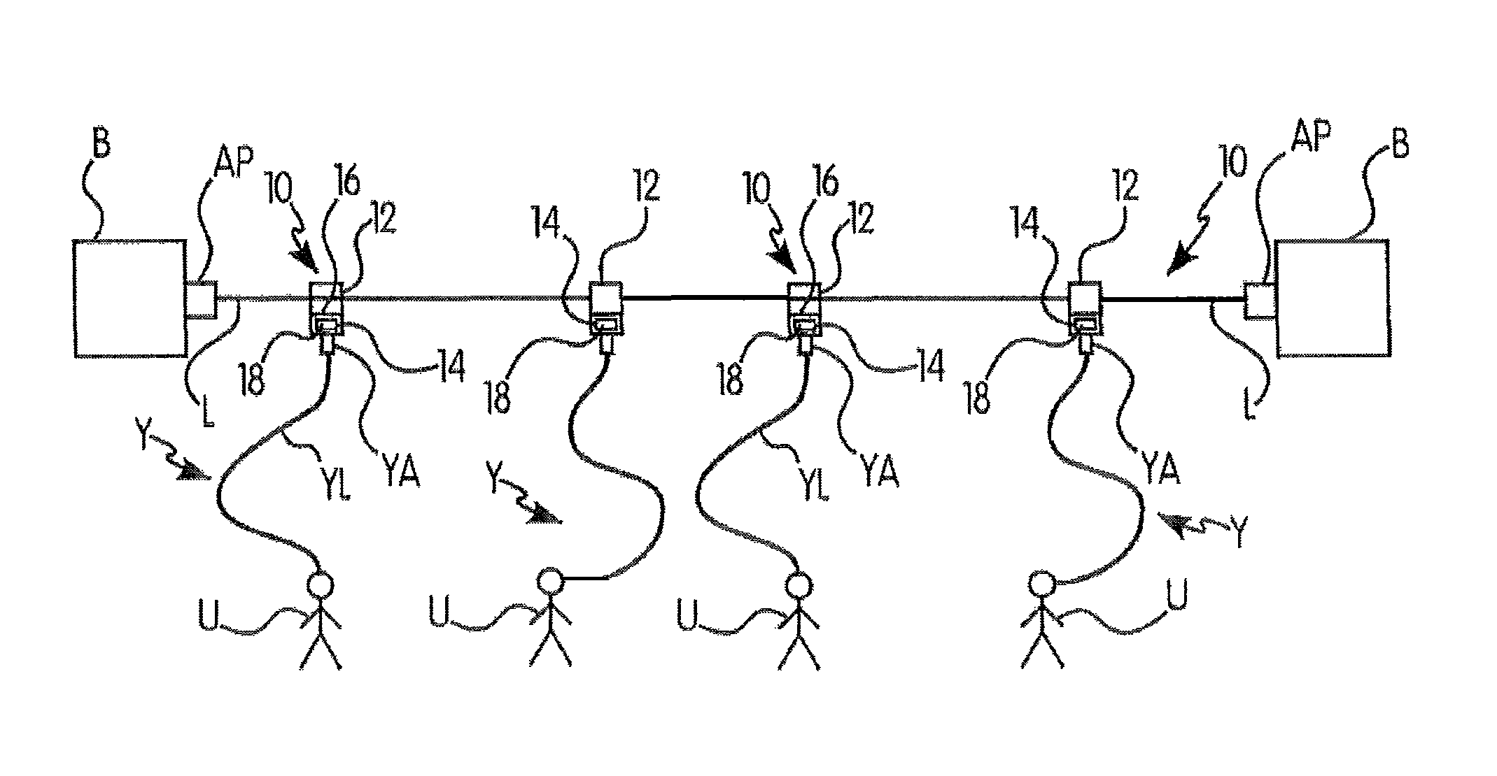
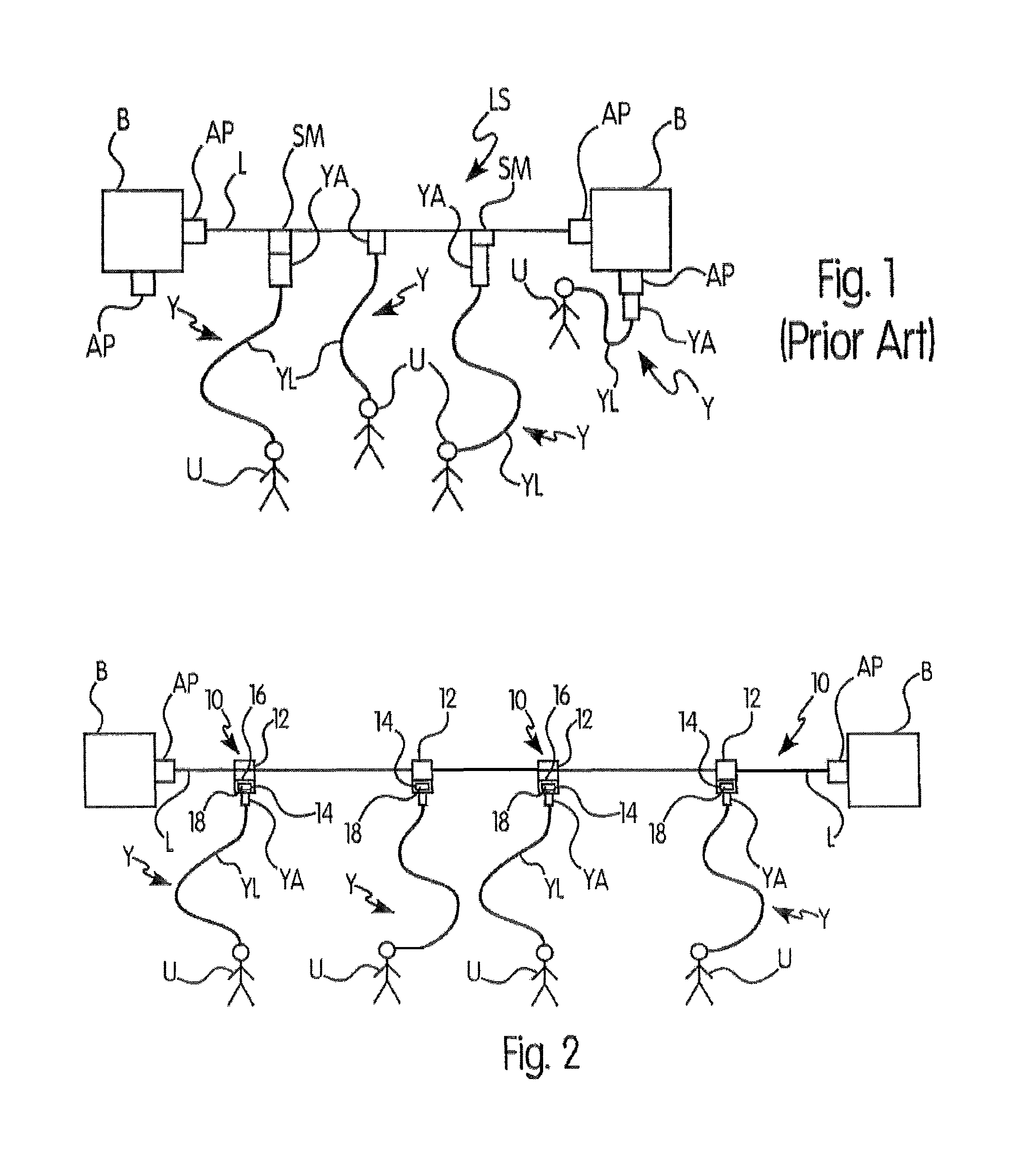
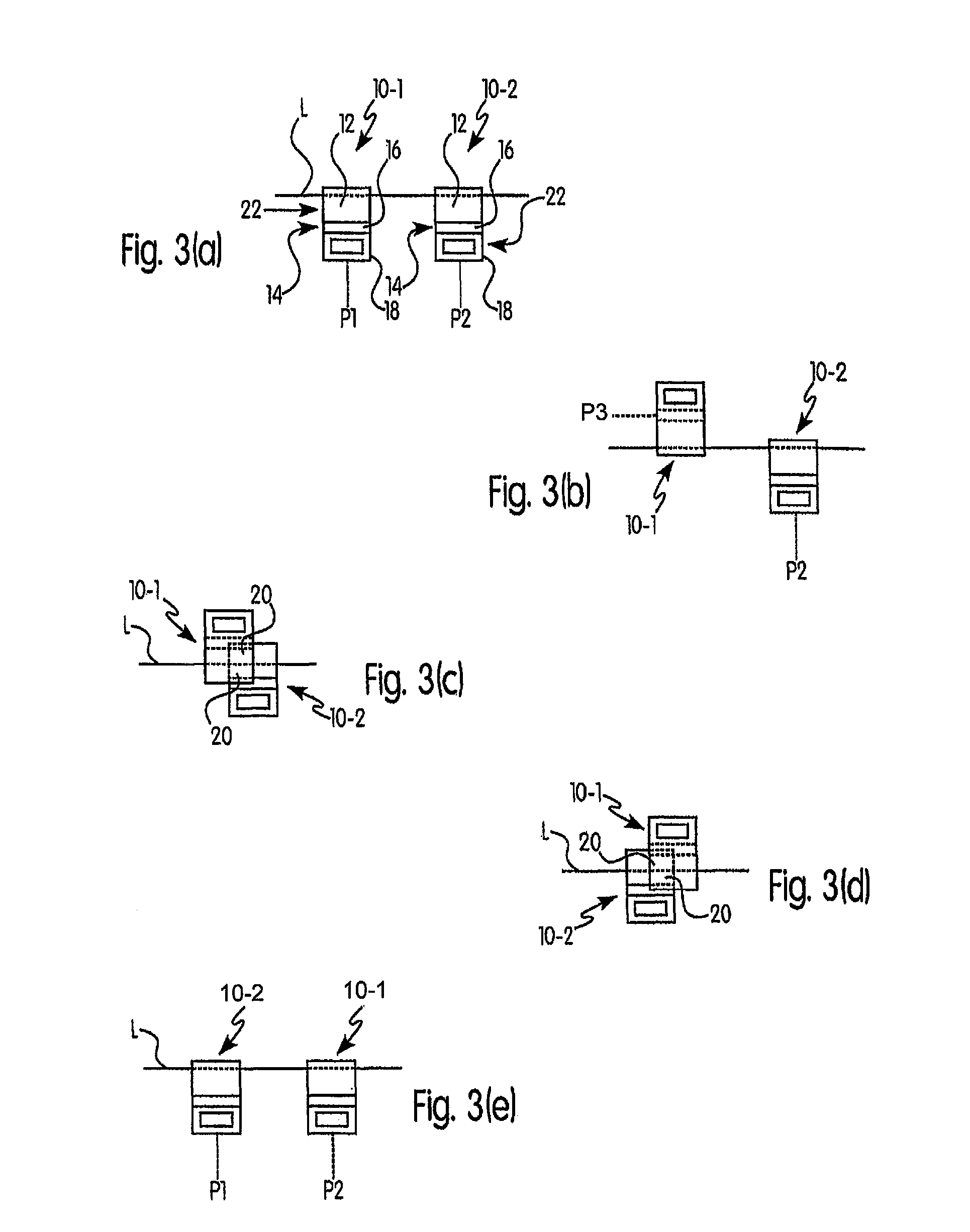
[0009]Generally, the present invention provides methods, apparatus and arrangements for a lifeline system that overcome some or all of the drawbacks and deficiencies existing in known systems. Preferably, the present invention provides methods, apparatus and arrangements for a lifeline system that permit the safe passage of multiple attaching devices connected to the same line or cable. Preferably, the present invention provides methods, apparatus and arrangements for a lifeline system that lead to increased safety, and are easy to implement and utilize. Preferably, the present invention provides methods, apparatus and arrangements for a lifeline system that are useful in connection with new or existing lifeline systems, such as a portable, temporary horizontal lifeline system.

Problems solved by technology

In the construction industry, one of the most dangerous aspects is working at great heights above the ground, e.g., high-level buildings, repair of certain large structures, etc.
Such a dangerous situation and environment exists in many different industries and activities as well.
However, as stated, in existing systems, more than one worker is often attached to a single lifeline, which leads to the need for workers to pass each other.
This obviously leads to increased time, decreased efficiency, and a greater possibility of some mishap when the workers are making the switch.

Method used


Image

  • Method, apparatus, and arrangement for a lifeline system
  • Method, apparatus, and arrangement for a lifeline system
  • Method, apparatus, and arrangement for a lifeline system

Examples


Embodiment Construction

[0035]For purposes of the description hereinafter, the terms “end”, “upper”, “lower”, “right”, “left”, “vertical”, “horizontal”, “top”, “bottom”, “lateral”, “longitudinal” and derivatives thereof shall relate to the invention as it is oriented in the drawing figures. However, it is to be understood that the invention may assume various alternative variations and step sequences, except where expressly specified to the contrary. It is also to be understood that the specific devices and processes illustrated in the attached drawings, and described in the following specification, are simply exemplary embodiments of the invention. Hence, specific dimensions and other physical characteristics related to the embodiments disclosed herein are not to be considered as limiting. For example, the term “end” may refer to the extreme distal portion or the area near or adjacent that portion. Further, it is to be understood that the invention may assume various alternative variations and step sequen...


PUM


Abstract

A shuttle member for a horizontal lifeline system having at least one elongate line attached between at least two anchorage points. The shuttle member includes: a body having: (i) an upper portion configured for attachment to the line by at least partially surrounding the line; (i) an intermediate portion that, together with the upper portion, defines at least one passage slit that is sized such that the elongate line cannot pass therethrough; and (iii) an attachment portion configured for attachment of at least a portion of a lanyard. A shuttle member arrangement and a passing method are also disclosed.

Description

BACKGROUND OF THE INVENTION[0001]1. Field of the Invention[0002]The present invention relates generally to fall protection systems and arrangements, and in particular to a method, apparatus and arrangement for use in connection with a lifeline system, preferably a horizontal lifeline system, and further to a shuttle member, a shuttle member arrangement, and a method of passing such shuttle members during use in such a lifeline system.[0003]2. Description of the Related Art[0004]In the construction industry, one of the most dangerous aspects is working at great heights above the ground, e.g., high-level buildings, repair of certain large structures, etc. The leading reason for injuries and fatalities within the construction industry is a fall from a high location. Such a dangerous situation and environment exists in many different industries and activities as well. Therefore, an important safety consideration is to protect the worker or other person operating or engaging in an activi...

Claims


Application Information

Patent Timeline
Patent Type & Authority Patents(United States)
IPC IPC(8): E04G21/32A62B35/00B61B7/00
CPCE04G21/3204A62B35/0087A62B35/0056A62B35/0081
Inventor BODNAR, JONATHANBRIDGES, ZOEHAIDARY, NADEEMJURA, JASONPARK, JUNG HWANZHOU, RUQIAN
Owner MSA TECH
Why Eureka
Try Eureka