Intradermal pen adapter

a pen adapter and pen technology, applied in the field of intradermal pen adapters, can solve the problems of failed injection, difficult intradermal injection, lost delivery compound on the skin surface,

Active Publication Date: 2014-11-04
SID TECH LLC
View PDF74 Cites 8 Cited by
  • Summary
  • Abstract
  • Description
  • Claims
  • Application Information

AI Technical Summary

Problems solved by technology

Making intradermal injections is difficult and generally requires an experienced nurse or medical professional.
Incorrect placement of the tip of the cannula may lead to a failed injection.
Incorrect placement of the cannula may also puncture the skin again after being inserted into dermis, with the delivered compound being lost on the surface of the skin.
The insertion of the cannula at an incorrect angle and / or depth results in a failed intradermal injection, which is typically repeated, causing additional pain and discomfort as well as ineffective treatment to the patient.
Intradermal (ID) injection has been considered for immunization in the past, but has generally been rejected in favor of more reliable intramuscular or subcutaneous routes of administration because of the difficulty in making a successful ID injections, particularly when the injections are administered by relatively unskilled healthcare professionals.
The technique is known to be quite difficult to perform and generally requires specialized training.
A degree of imprecision in the placement of the injection results in a significant number of false negative test results.

Method used


Image

  • Intradermal pen adapter
  • Intradermal pen adapter
  • Intradermal pen adapter

Examples


second embodiment

[0045]Referring to FIGS. 6 and 7, in a second preferred embodiment, an adapter 10′ has a similar configuration to the adapter 10 of the first preferred embodiment, but the cannula 14′ is fixed to the adapter 10′, the body 16′ does not include a side opening for receipt of the syringe 12′, as well as additional structural and functional differences between the first and The adapter 10′ of the second preferred embodiment utilizes the same reference numerals to identify similar features relative to the adapter 10 of the first preferred embodiment and a prime symbol (′) to specifically identify the adapter 10′ of the second preferred embodiment and its components. Accordingly, a significant number of the features of the second preferred embodiment of the adapter 10′ are the same or similar to the adapter 10 of the first preferred embodiment and the features that are different in the adapter 10′ of the second preferred embodiment are emphasized in the below description.

[0046]In the seco...

first embodiment

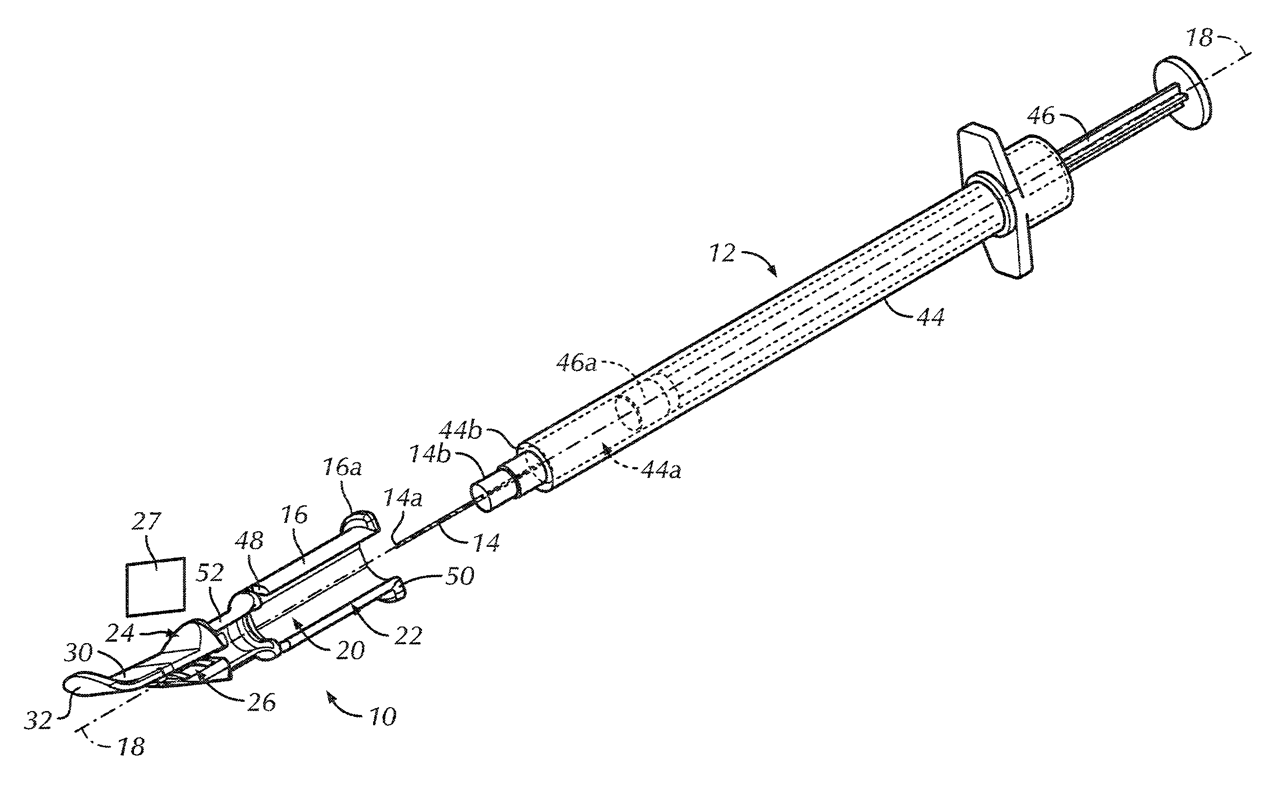
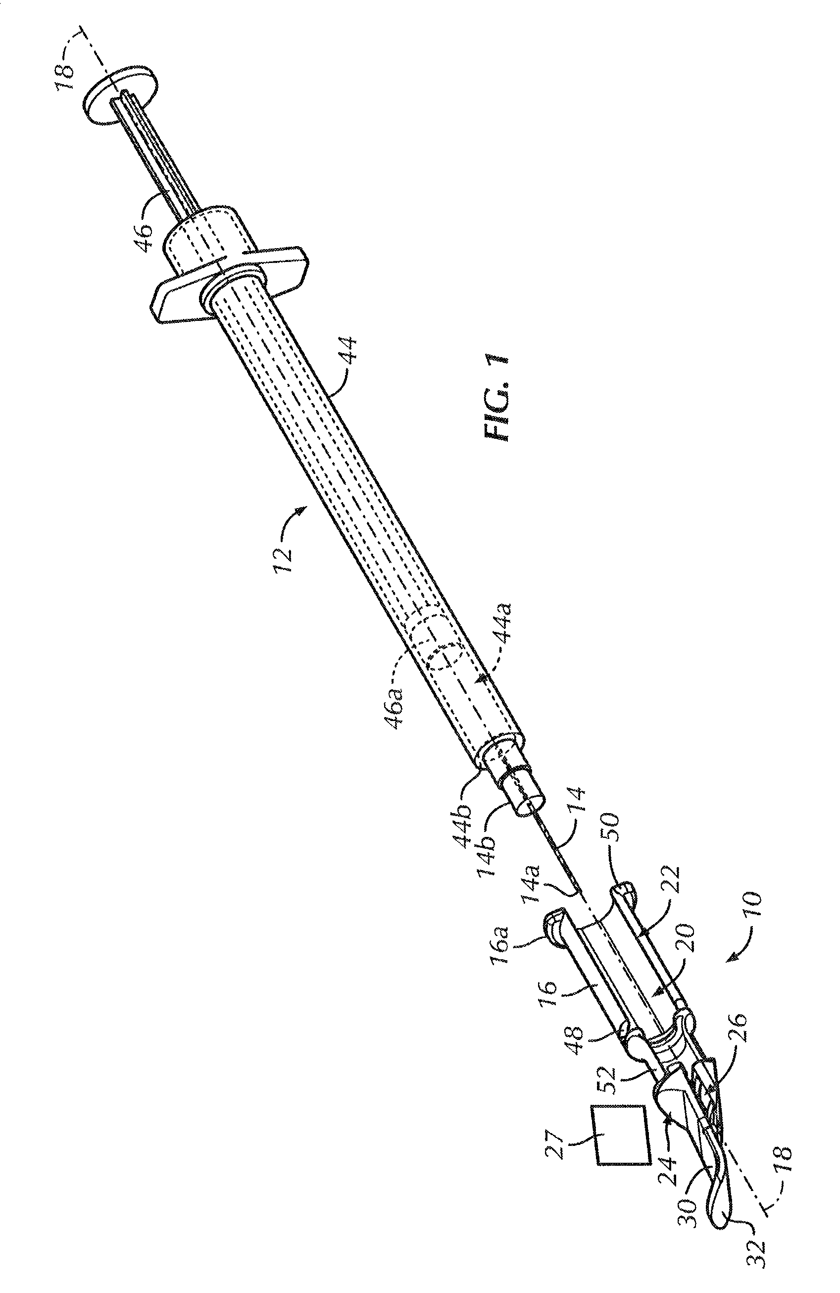
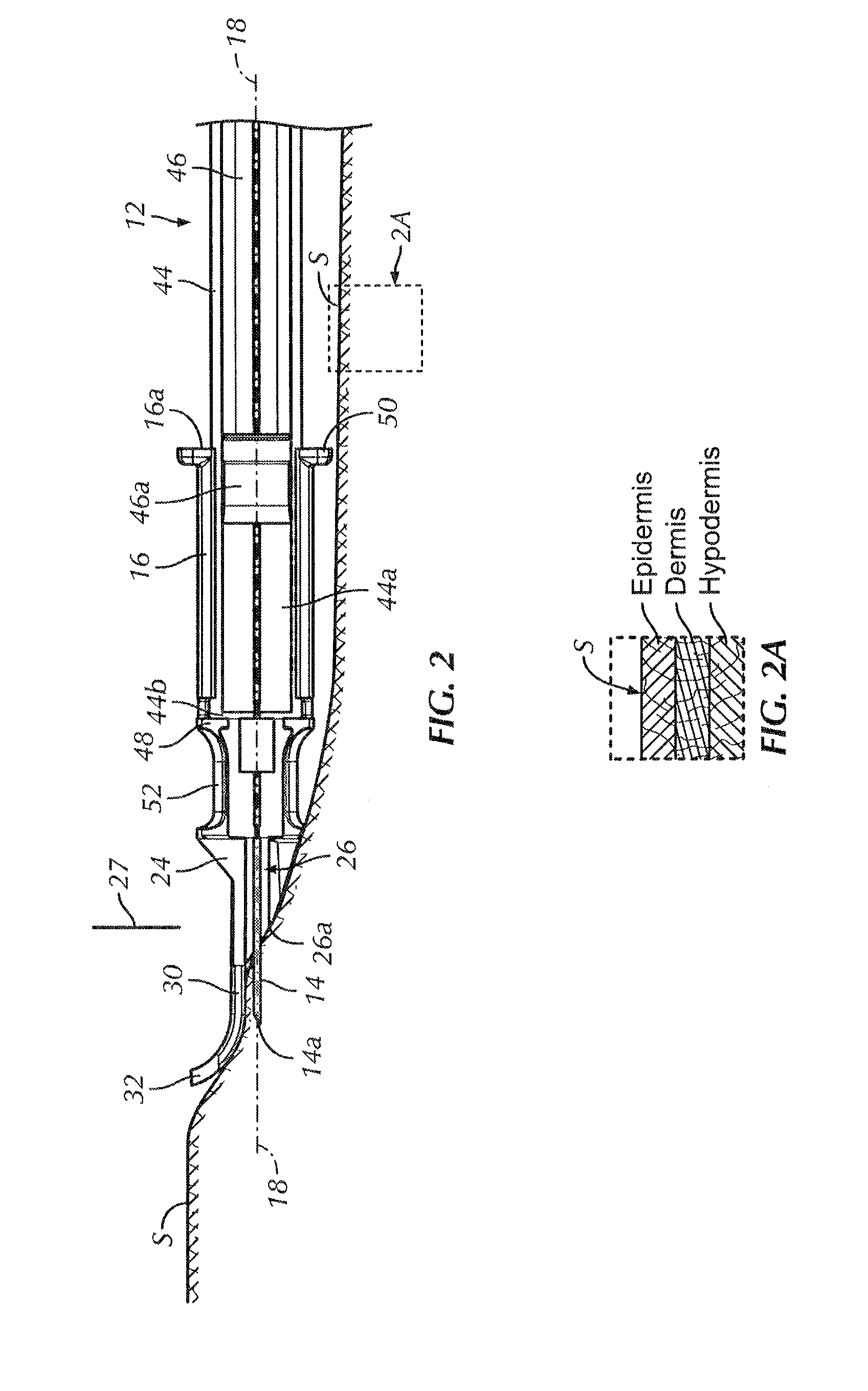
[0053]Referring to FIGS. 1-5, in operation of the adapter 10, the syringe 12 is either provided pre-filled or the medicament is aspirated into the syringe 12 from a vial (not shown). The syringe 12 may be separate from the adapter 10 to aspirate the medicament into the syringe 12 and a different cannula 14 may be utilized to aspirate the medicament into the syringe 12 than is used to inject the medicament into the patient. For example, a relatively large gage cannula 14 may be used to aspirate the medicament into the barrel 44 and the relatively large gage cannula 14 may be replaced with a smaller gage cannula 14 for injection. Alternatively, the central portion 24 and distal protrusion 30 may be hingedly mounted to the barrel 44 and / or hub 14b and the cannula 14 such that the central portion 24 and distal protrusion 30 may be pivoted away from the cannula 14 during aspiration of medicament from the vial into the syringe 12 and then pivoted back into the assembled configuration for ...


PUM


Abstract

An intradermal injection adapter includes a body having a longitudinal axis and a central portion located distally relative to the body along the longitudinal axis. The central portion has a cannula channel therethrough extending generally parallel to the longitudinal axis. A cannula within the cannula channel has a sharpened tip for injection into a patient and a sharpened opposite proximal end for injection into a pen injector. A distal protrusion has a first skin contacting surface extending generally parallel to the longitudinal axis. The first skin contacting surface is spaced from the cannula such that a distal portion of the cannula extends generally parallel to the first skin contacting surface.

Description

CROSS-REFERENCE TO RELATED APPLICATIONS[0001]This application is a Non-Provisional of Provisional Application No. 61 / 461,650, entitled “Intradermal Pen Adapter”, filed Jan. 21, 2011, the contents of which are incorporated herein by reference in their entirety.BACKGROUND OF THE INVENTION[0002]Intradermal injections are used for delivering a variety of diagnostic and treatment compositions into a patient. Intradermal injections are typically injections of a relatively small amount of medicament into the dermis or dermal layer or even into a lower portion of the epidermis (FIG. 2A) of a patient's skin. Substances may be injected intradermally for diagnostic testing, such as to determine a patient's immunity status against tuberculosis and the status of allergic diseases. Vaccines, drugs and other compounds may also be delivered intradermally. In many instances, intradermal delivery is preferred because it generally requires a smaller volume dose of the diagnostic or treatment compound ...

Claims


Application Information

Patent Timeline
Patent Type & Authority Patents(United States)
IPC IPC(8): A61M5/158A61M5/32A61M5/00A61M5/46A61B5/15A61B5/153
CPCA61B5/150748A61M5/3287A61B5/153A61M5/46A61B5/150183A61B5/150068A61M5/158
Inventor TSALS, IZRAILEVANS, CHRISTOPHERCOSTELLO, BRIAN
Owner SID TECH LLC
Why Eureka
Try Eureka