
Chandelier lamp system

a technology for chandeliers and light fixtures, applied in the field of improved and energy efficient lamp systems, can solve the problems of fluorescent chandelier light bulbs not providing the unique features of traditional chandelier light bulbs, chandelier lamps are the most inefficient light fixtures in use today, and extreme inefficiency of light bulbs

Inactive Publication Date: 2014-11-04
LU SUN +1
View PDF2 Cites 7 Cited by
  • Summary
  • Abstract
  • Description
  • Claims
  • Application Information

AI Technical Summary

Benefits of technology

The patent describes a chandelier lamp that has three light emitting diodes (LEDs) that produce red, green, and blue colors. These LEDs can be controlled by a controller that provides instructions to them. The LEDs can be programmed to produce different lighting effects and can change colors according to pre-programmed time sequences. Additionally, the LEDs have special optical components that reflect, diffuse, and bend the light from the LEDs to create a sparkling appearance that mimics the effects of traditional chandelier light bulbs with tungsten filaments. The technical effects of this patent are an improved method for controlling the LEDs in a chandelier lamp and the creation of a more realistic decorative lighting effect with many different colors that can change over time.

Problems solved by technology

By today's standard, these are extremely inefficient light bulbs.
That makes the chandelier lamps the most inefficient light fixtures in use today.
However, they provide the unique decorative effects that can not be matched by any other light fixtures.
However, the fluorescent chandelier light bulbs do not provide the unique features of the traditional chandelier light bulbs.
This finish is very detrimental and does not give the sparkling feeling of the tungsten chandelier light bulb.
Third, most of these fluorescent chandelier light bulbs run at 4 Watts.
Therefore, the light can appear to be dim to people used to using the prior bulbs and it is difficult to add bulbs to a lamp.
Fourth, it is difficult to dim the fluorescent lamps to create the romantic and traditional decorative effect.
With these issues, the fluorescent chandelier light bulb, even it is 400% more energy efficient, is not a good replacement of the tungsten chandelier light bulbs.
Currently, there is no large commercial distribution of chandelier light bulbs using light emitting diodes “LEDs”.
The fundamental reason is perhaps that an LED light bulb with 300-600 Lumens light output is still very expensive today.

Method used


Image

  • Chandelier lamp system
  • Chandelier lamp system
  • Chandelier lamp system

Examples


Embodiment Construction

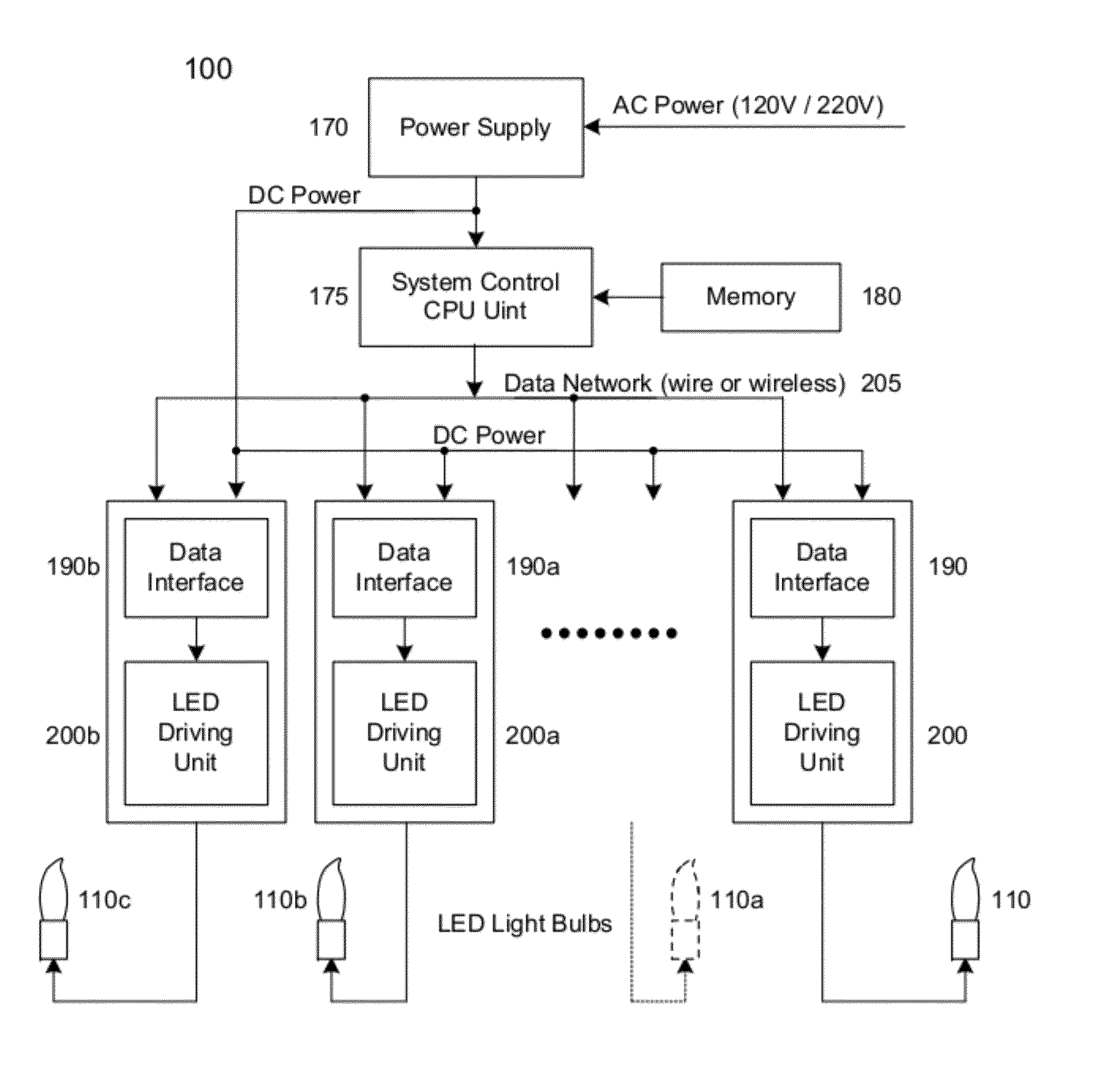
[0038]This present disclosure is directed to an improved chandelier lamp system 100. The chandelier lamp system 100 has a traditional chandelier lamp appearance, but the system 100 also includes a control system and network architecture that can create one or more lighting effects that are aesthetically pleasing.

[0039]The chandelier lamp system 100 preferably includes at least three light emitting diodes with red, green, and blue (R, G, B) light emitting diodes. The R, G, B light emitting diodes in the light bulb are driven with three separate driving circuits which can control the brightness level of the emitted light from each color LED independently. Thus, the light emitted from the bulb is a mixture of R, G, B colors at various ratios and when combined can have many different colors.

[0040]The chandelier light bulb preferably has the red, green and blue light emitting diodes in a transparent envelope having the same shape as a traditional chandelier light bulb to preserve the dec...


PUM


Abstract

A method includes providing a chandelier comprising at least three light emitting diodes, with each of the at least three light emitting diodes having at least one color of red, green, and blue colors. The method also includes operatively connecting the light emitting diode to a controller and a memory such that the controller provides control instructions to the light emitting diodes. The method also has controlling the at least three light emitting diodes to provide a decorative lighting effect.

Description

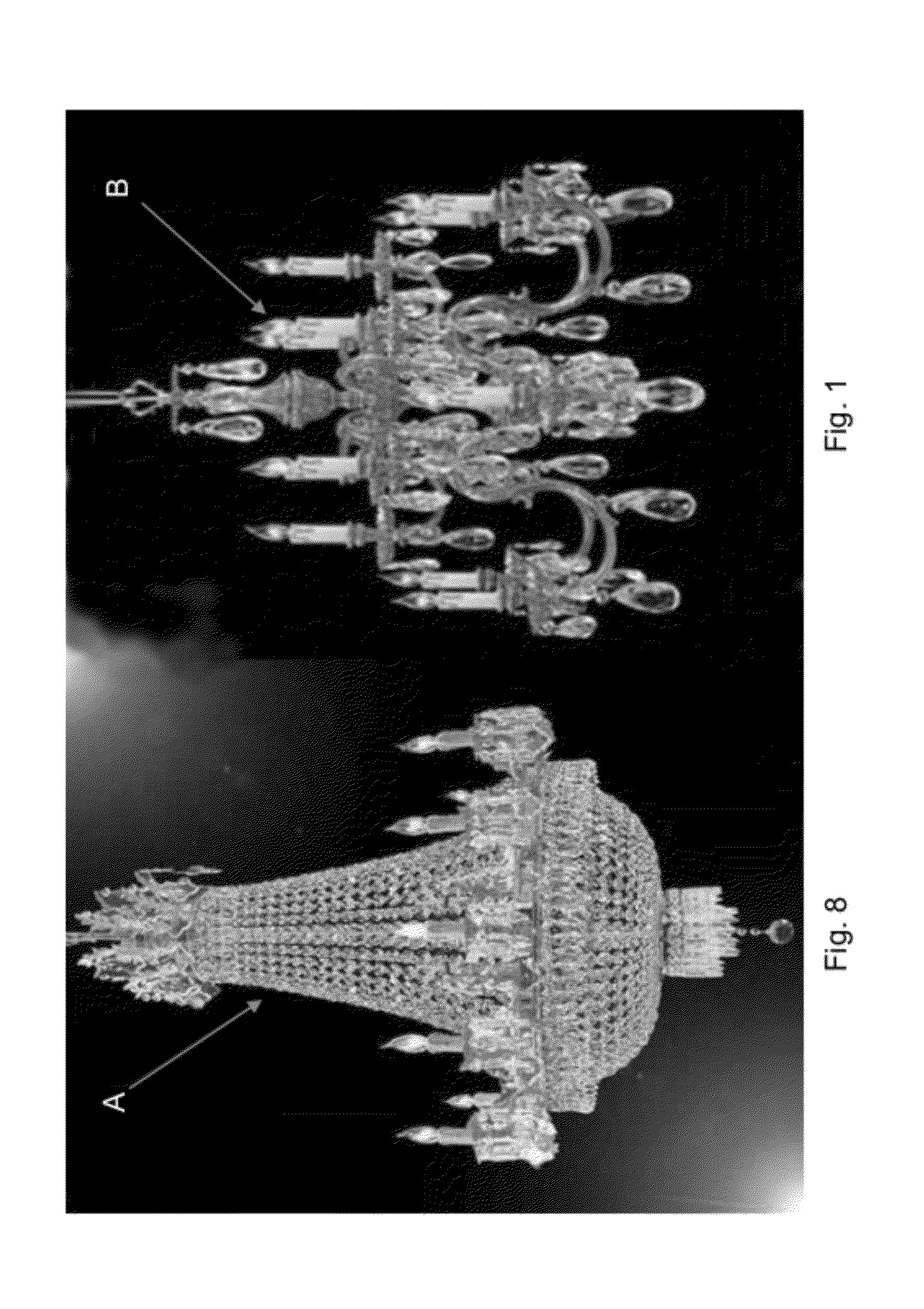
CROSS REFERENCE TO RELATED PATENT APPLICATIONS[0001]This patent application claims priority to U.S. Provisional Patent Application No. 61 / 378,840 to Lu filed on Aug. 31, 2010 , which is incorporated by reference in its entirety.FIELD OF THE INVENTION[0002]The present disclosure is directed to an improved and energy efficient lamp system that mimics a traditional chandelier. More particularly, the present disclosure is directed to a chandelier that includes a number of light emitting diodes in different colors in a bulb envelope being controlled by a controller.BACKGROUND OF THE RELATED ART[0003]Chandelier lamps are very popular in homes and commercial places for decorative effects. An example of two chandelier lamps are shown as prior art in FIGS. 1 and 8 as reference letters A and B. Conventional chandelier lamps are traditionally hung from a ceiling or the like and use special shaped tungsten light bulbs with some cylindrical shaped stands below to mimic the candle lights. The tun...

Claims


Application Information

Patent Timeline
Patent Type & Authority Patents(United States)
IPC IPC(8): F21S10/04H05B33/08F21S8/06F21S6/00H01K1/30H05B37/00H05B37/02H05B44/00
CPCF21S6/001F21S10/04F21S8/065H05B37/029H05B33/0857H05B37/0272F21W2121/00H05B45/20H05B47/19H05B47/155
Inventor LU, SUNHOU, WEN-CHAU WAYNE
Owner LU SUN
Learn More