Tube couplings

a technology of couplings and tubes, applied in the direction of couplings, sleeves/socket joints, pipe joints, etc., can solve problems such as difficulties in establishing a reliable connection

Inactive Publication Date: 2014-11-11
JOHN GUEST INT LTD
View PDF16 Cites 11 Cited by
  • Summary
  • Abstract
  • Description
  • Claims
  • Application Information

AI Technical Summary

Benefits of technology

[0006]A coupling of the kind described is disclosed in EP 1 310 720. This design is a development of our “Speedfit” connector as disclosed in GB 1 520 742. It is designed to provide a seal against the end of the inserted tube. This eliminates the void which is otherwise present around the end of the tube and O-ring seal. Further, the seal creates a generally smooth throughbore with the tube. Such a void free construction provides no regions where fluid may congregate and the relatively smooth flow path is easier to clean.
[0009]With such an arrangement, the collet is held more reliably against the tapered surface in the cap as the tube is inserted. Maintaining the collet legs more reliably in contact with the tapered surface means that the amount of travel of the cap is directly related to the degree of compression of the seal as no movement is “wasted” in closing the gap between the collet and the cap. This allows the correct amount of compression of the seal to be achieved with greater reliability.
[0010]The member which provides the biasing force may be positioned anywhere in which it is able to provide the necessary biasing force. For example, it may be outside the cap such that it acts between an end surface of the cap and an outwardly projecting shoulder on a projecting portion of the collet. However, preferably, the member which provides the biasing force is within the cap as this protects it from damage and the ingress of dirt and debris.
[0014]When the member which provides a biasing force is tubular and is within the coupling body, this is beneficial in providing radial location and support for the tube.
[0015]The member which provides the biasing force may be made of a continuous compressible material, but is preferably a spring (e.g., a helically coiled spring, an undulating ring, or a ring of opposing crosses). This spring can be arranged such that, in the forward position of the cap, no further compression of the spring is possible. This eliminates any possibility of further inward movement of the collet against the spring thereby serving to lock the collet in position.

Problems solved by technology

However, there have been some difficulties in establishing a reliable connection.

Method used


Image

  • Tube couplings
  • Tube couplings
  • Tube couplings

Examples


Embodiment Construction

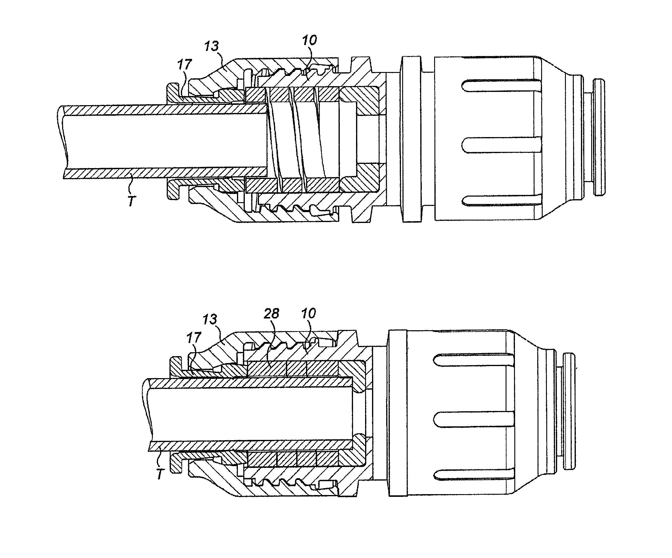
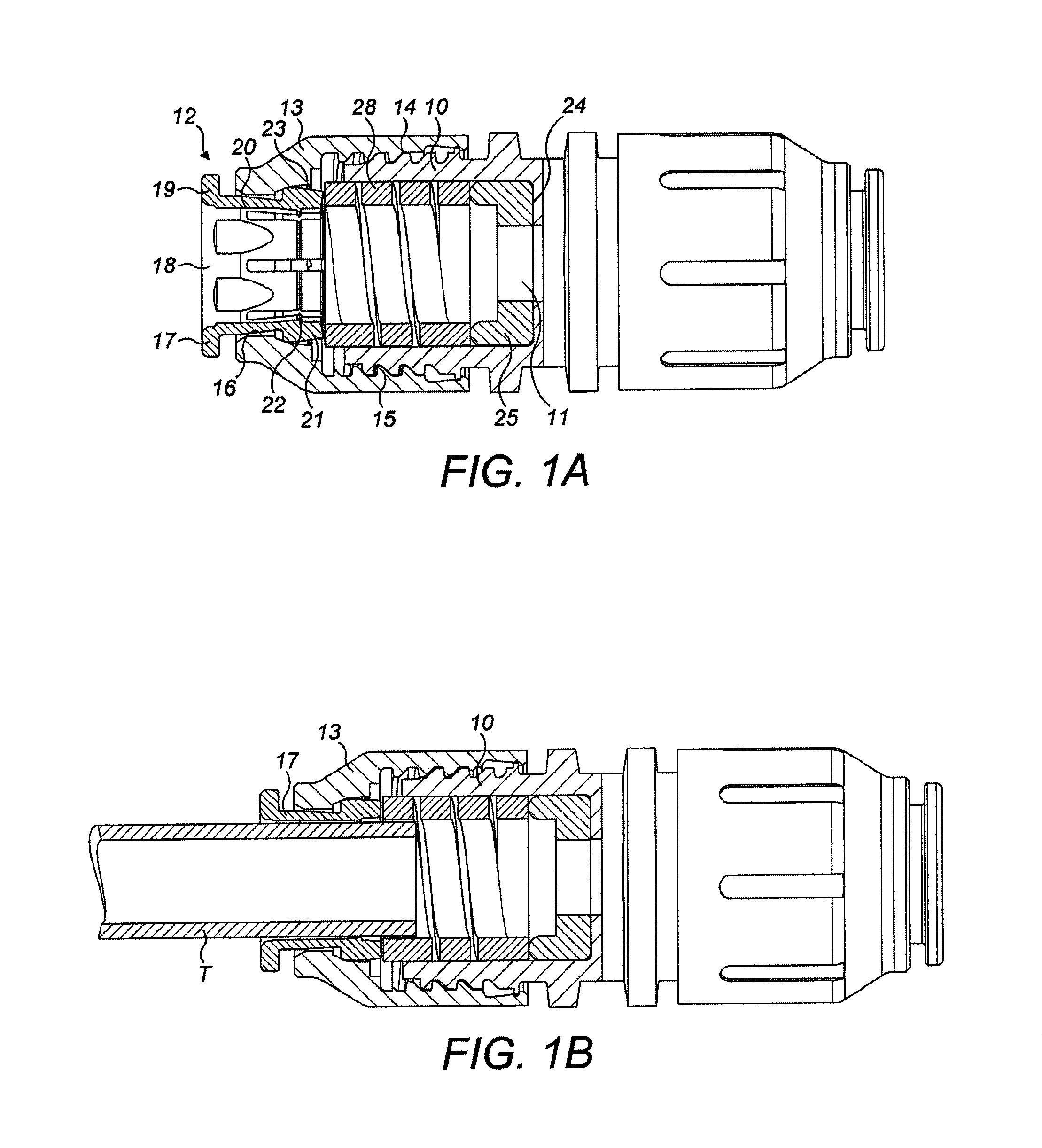
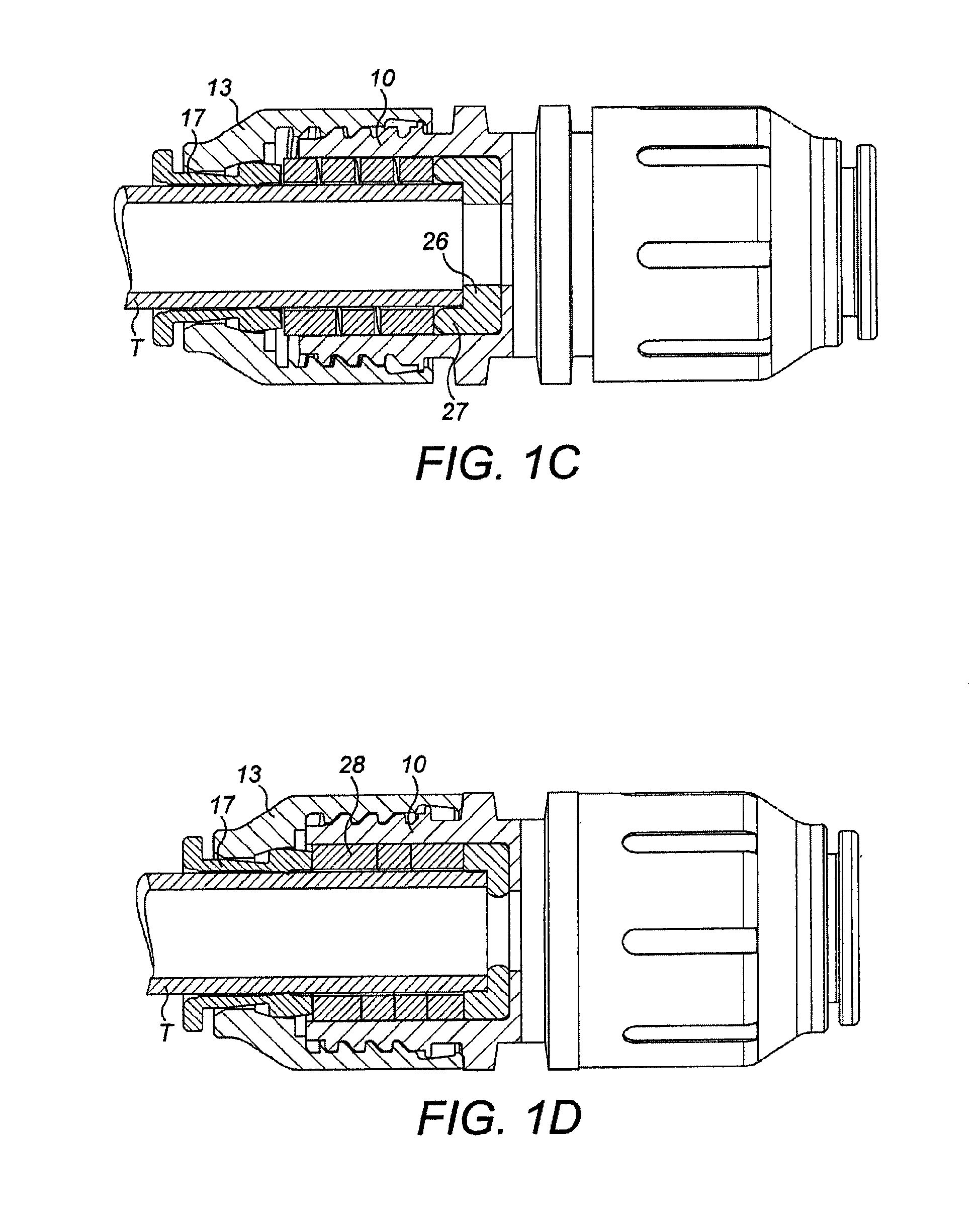
[0024]In all figures, the connectors illustrated are in-line connectors. For simplicity, only the left-hand side of the connector is shown in cross section. The right-hand side of the connector may have the same configuration or may be provided with a different connection mechanism as necessary. The same connector design may equally be applied to elbow or T-couplings or tube closures where again one or more of the connections is as described and others may be of different designs as necessary.

[0025]The connector comprises a coupling body 10 having a throughway 11 open at one end 12 to receive internally an end portion of the tube T and externally an end cap 13. The coupling body 10 has an external screw thread 14 which engages with a complimentary internal thread in the end cap 13. The end cap 13 has a central opening 16 in which a collet 17 is received. The collet 17 comprises an annular portion 18 extending through the opening 16 and has an outwardly projecting annular flange 19 w...


PUM


Abstract

A tube coupling to receive and hold a tube (T) includes a coupling body (10) having a throughway with an annular step (24) facing an open end (12). An annular seal (25) is located in the coupling body adjacent to the annular step. An end cap (13) engages the coupling body and is axially moveable. A collett (17) in the cap has legs (20) with outer surfaces that engage with a tapered surface (23) in the end cap to urge the legs inwardly to grip the tube. The seal (25) is compressed axially in response to the forward movement of the end cap (13) to cause the tube end to be pressed into sealing engagement with the seal end. A biasing member (28) provides a biasing force to urge the legs (20) axially onto the tapered surface (23) when the cap is in the retracted position.

Description

CROSS-REFERENCE TO RELATED APPLICATIONS[0001]This application claims priority to United Kingdom Application No. 1205577.8, filed Mar. 29, 2012, which is incorporated herein by specific reference.BACKGROUND OF THE INVENTION[0002]1. The Field of the Invention[0003]This invention relates to tube couplings which may be single or multiple tube couplings providing in-line, elbow or T-couplings or tube closures.[0004]2. The Relevant Technology[0005]More specifically, the present invention relates to a tube coupling to receive and hold a tube comprising a coupling body having a throughway open at one end to receive an end portion of tube, an annular step in the throughway facing the open end to provide an end stop for a tube, an annular seal located in the coupling body adjacent to the annular step, an end cap engaging the coupling body for axial movement between forward and retracted positions on the body, the end cap having an opening for the end portion of the tube to extend therethrough...

Claims


Application Information

Patent Timeline
Patent Type & Authority Patents(United States)
IPC IPC(8): F16L37/092F16L21/06F16L37/10
CPCF16L37/0925F16L37/101F16L37/0927F16L37/086F16L37/02F16L21/08
Inventor GUEST, TIMOTHY, STEVEN
Owner JOHN GUEST INT LTD
Why Eureka
Try Eureka