Articulating disc implant

a technology of disc implants and articulating discs, applied in the field of joint prosthesis and intervertebral implants, can solve the problems of loss of lower back mobility, damage or dislocation of spinal discs, and current prosthetic disc implants that do not replicate the range of motion undertaken by healthy spinal vertebra

Active Publication Date: 2014-11-11
DEPUY SYNTHES PROD INC
View PDF107 Cites 2 Cited by
  • Summary
  • Abstract
  • Description
  • Claims
  • Application Information

AI Technical Summary

Problems solved by technology

Due to general wear and tear, spinal discs can become damaged or dislocated giving rise to a problem commonly referred to as a “slipped disc”.
However, this method resulted in a loss of mobility in the patient's lower back.
However, current prosthetic disc implants do not replicate the ranges of motion undertaken by healthy spinal vertebrae.

Method used


Image

  • Articulating disc implant
  • Articulating disc implant
  • Articulating disc implant

Examples


Embodiment Construction

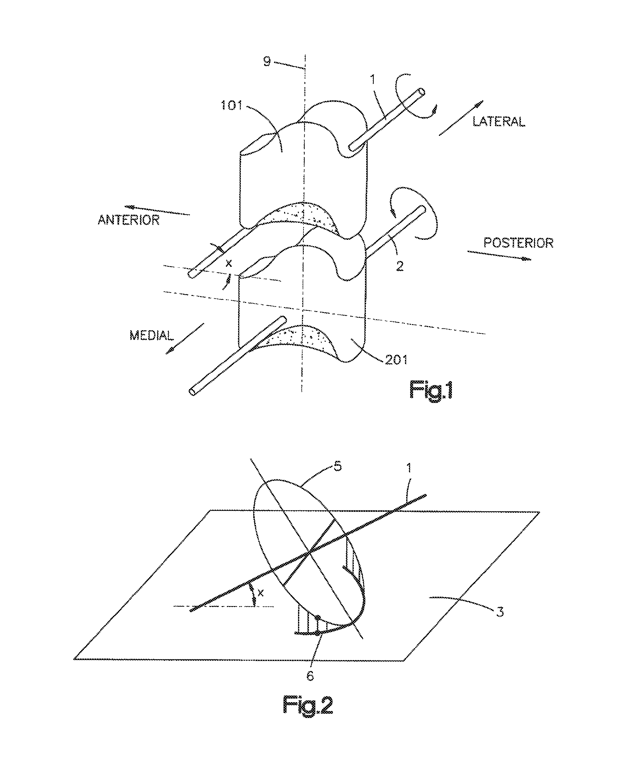
[0047]Certain terminology is used in the following description for convenience only and is not limiting. The words “right”, “left”, “lower”, “upper”, “bottom”, and “top” designate directions in the drawings to which reference is made. The words “inwardly” and “outwardly” refer to directions toward and away from, respectively, the geometric center of the bone fixation element, instruments and designated parts thereof. The words, “anterior”, “posterior”, “superior”, “inferior”, “medial”, “lateral” and related words and / or phrases designate preferred positions and orientations in the human body to which reference is made and are not meant to be limiting. The terminology includes the above-listed words, derivatives thereof and words of similar import.

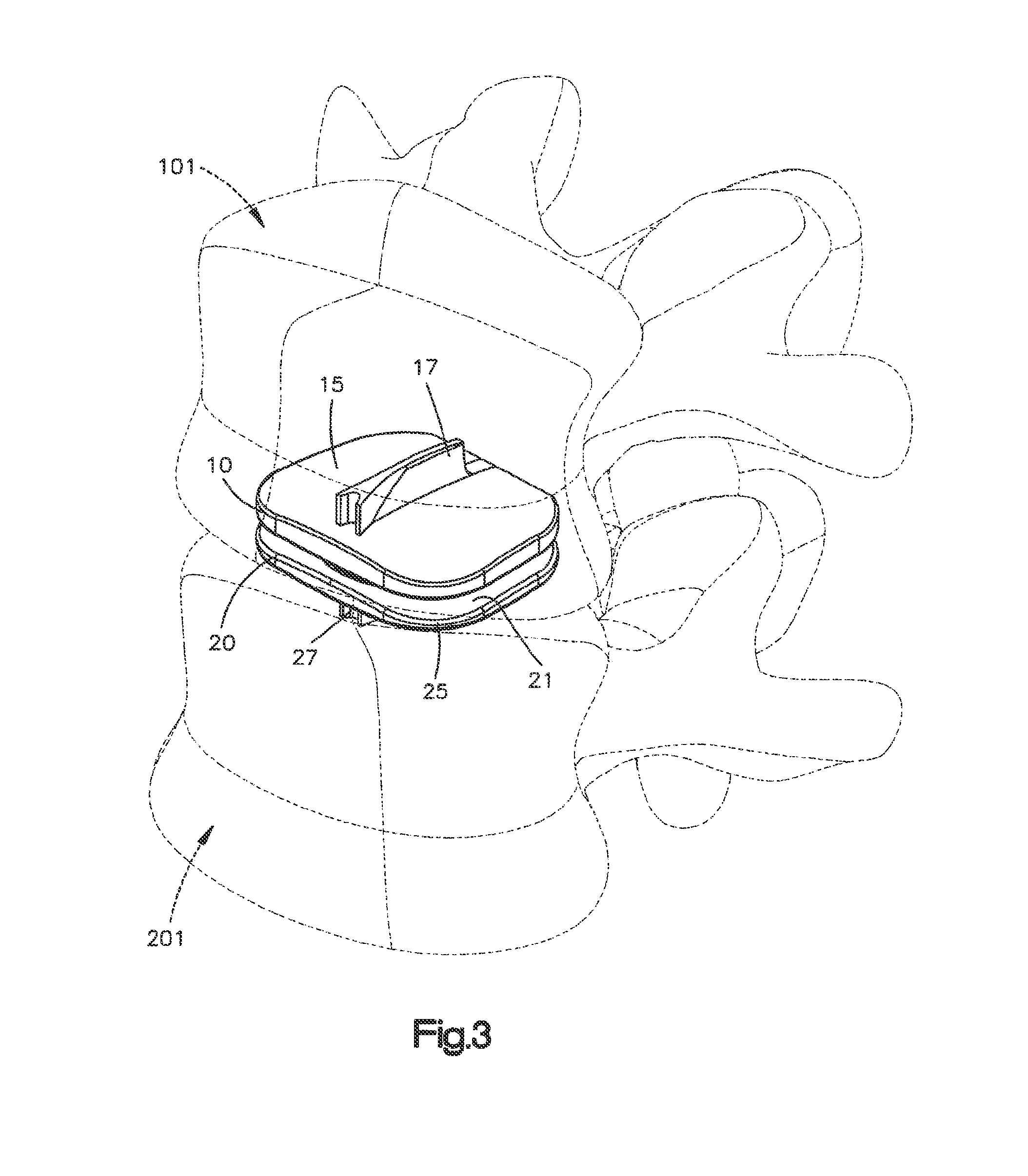
[0048]FIG. 1 illustrates two adjacent cervical vertebrae, vertebra 101 and vertebra 201, which are located in the spine. Vertebrae 101 and 201 typically have a spinal disc (not shown) positioned between them that form a spinal segment that ...


PUM


Abstract

An intervertebral disc implant for use in the spine including a first part and a second part, wherein the first part and second part are configured as a joint prosthesis for the spine. The first part includes one of a concave or convex articulating surface and the second part includes one of the other concave or convex articulating surface. One of the concave or convex articulating surfaces is preferably elliptically shaped in at least one direction and does not match and is different than one of the other concave or convex articulating surfaces.

Description

CROSS-REFERENCE TO RELATED APPLICATIONS[0001]This application is a continuation-in-part of U.S. patent application Ser. No. 12 / 995,723, filed Dec. 2, 2010, which is a National Stage of International Application No. PCT / US2009 / 046442, filed Jun. 5, 2009, which claims the benefit of U.S. Provisional Application No. 61 / 059,024, filed Jun. 5, 2008, the disclosures of which are incorporated herein by reference in their entireties for all purposes.FIELD OF THE INVENTION[0002]This invention relates to an implant, more specifically a joint prosthesis, more specifically an intervertebral implant, and even more specifically a joint prosthesis to replace a spinal disc.BACKGROUND OF THE INVENTION[0003]Due to general wear and tear, spinal discs can become damaged or dislocated giving rise to a problem commonly referred to as a “slipped disc”. Intervertebral spinal discs lie between adjacent vertebrae in the spine. Each disc forms a cartilaginous joint allowing slight movement of the vertebrae an...

Claims


Application Information

Patent Timeline
Patent Type & Authority Patents(United States)
IPC IPC(8): A61F2/30A61F2/44A61F2/28
CPCA61F2/28A61F2002/30884A61F2002/30654A61F2/4425A61F2002/30245A61F2002/3065A61F2310/00179A61F2002/302A61F2002/30934A61F2310/00359A61F2310/00029A61F2002/30253
Inventor REICHEN, MARCSCHMURA, KURT
Owner DEPUY SYNTHES PROD INC
Why Eureka
Try Eureka