Liquid crystal display device

a display device and liquid crystal technology, applied in liquid crystal compositions, instruments, chemistry apparatus and processes, etc., can solve the problems of color filter layer display defect, white spot, not much different, etc., to prevent the occurrence of display defects and the effect of reducing the voltage holding ratio

Active Publication Date: 2014-11-11
DIC CORPORATION
View PDF22 Cites 20 Cited by
  • Summary
  • Abstract
  • Description
  • Claims
  • Application Information

AI Technical Summary

Benefits of technology

[0018]A liquid crystal display device according to the present invention is capable of preventing a decrease in voltage holding ratio (VHR) of a liquid crystal layer and an increase in ion density (ID) by using a specified liquid crystal composition and a color filter including a specified dye and / or pigment, thereby preventing the occurrence of display defects such as white spots, alignment unevenness, image sticking, and the like.

Problems solved by technology

Therefore, the color filter layer and the liquid crystal layer are not put in a completely isolated environment, and the color filter layer has the possibility of developing display defects such as white spots, alignment unevenness, image sticking, and the like due to a decrease in voltage holding ratio (VHR) of the liquid crystal layer and an increase in ion density (ID) which are caused by impurities contained in the color filter layer through the alignment film and the transparent electrode.
However, these methods are not much different from a method of simply decreasing impurities in a pigment, and are thus unsatisfactory for improvement for resolving the display defects even in the present situation in which a pigment purifying technique has recently been advanced.
However, these cited documents each disclose an invention based on the principle that the influence of impurities in a pigment on a liquid crystal layer is suppressed and disclose no research on a direct relation between a structure of a liquid crystal material and a structure of a colorant such as a dye / pigment or the like used in a color filter, not leading to the resolution of the problem of display defects in advanced liquid, crystal display devices.

Method used


Image

  • Liquid crystal display device
  • Liquid crystal display device
  • Liquid crystal display device

Examples


examples

[0096]A best mode of the present invention is partially described in detail below by way of examples, but the present invention is not limited to these examples. In the examples and comparative examples below, “%” in a composition represents “% by mass”.

[0097]The physical properties of a liquid crystal composition are represented as follows.

[0098]TN-I: nematic-isotropic liquid phase transition temperature (° C.) as liquid crystal phase upper limit temperature

[0099]Δ∈: dielectric constant anisotropy

[0100]Δn: refractive index anisotropy

[0101]η: viscosity at 20° C. (mPa·s)

[0102]dgap: gap between first substrate and second substrate of cell (μm)

[0103]VHR: voltage holding ratio at 70° C. (%)

[0104](a value by % representing a ratio of a measured voltage to an initial applied voltage, the measured voltage being measured using a liquid crystal composition injected into a cell having a cell thickness of 3.5 μm under the conditions of 5 V applied, a frame time of 200 ms, and a pulse width of ...

examples 1 to 4

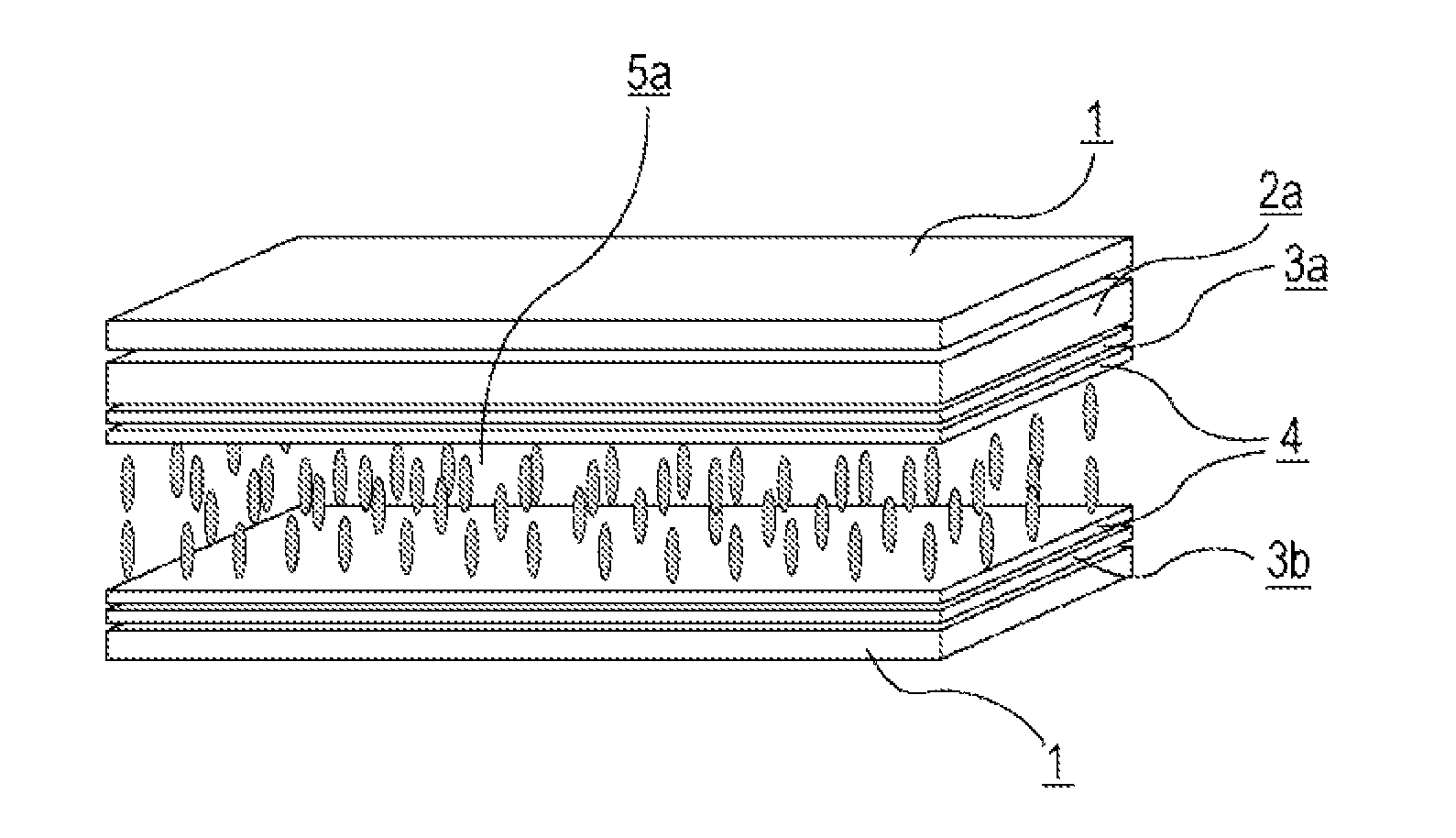
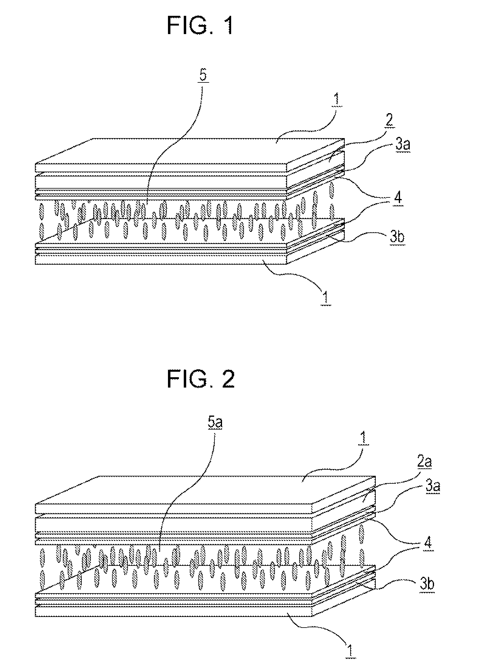
[0138]An electrode structure was formed on each of first and second substrates, and a vertical alignment-type alignment film was formed on each of the facing surfaces of the substrates and weakly rubbed to form a VA cell. Then, liquid crystal composition 1 having negative dielectric anisotropy and shown in Table 2 was held between the first, substrate and the second substrate. Next, liquid crystal display devices of Examples 1-4 were formed by using the color filters 1 to 4 shown in Table 1 (dgap=3.5 μm, alignment film SE-5300). VHR and ID of the resultant liquid crystal display devices were measured. Also, image sticking of the resultant liquid crystal display devices was evaluated. The results are shown in Table 3.

[0139]

TABLE 2Liquid crystalcomposition0d1-Cy-Cy-3203-Cy-Cy-2153-Cy-Ph-O150d1-Cy-1O-Ph5-O1-Cy-2110d1-Cy-1O-Ph5-O1-Cy-3110d1-Cy-1O-Ph5-O1-Cy-4110d1-Cy-1O-Ph5-O1-Cy-5110d1-Cy-Cy-1O-Ph5-O3d040d1-Cy-Cy-1O-Ph5-O4d040d1-Cy-1O-Ph5-O1-Cy-Cy-240d1-Cy-1O-Ph5-O1-Cy-Cy-34Composition ...

examples 5 to 12

[0154]As in Example 1, each of liquid crystals with negative dielectric anisotropy shown in Table 10 was held, and liquid crystal display devices of Examples 5 to 12 were formed by using the color filters shown in Table 1. VHR and ID of the resultant liquid crystal display devices were measured. Also, image sticking of the resultant liquid crystal display devices was evaluated. The results are shown in Tables 11 and 12.

[0155]

TABLE 10Liquid crystalLiquid crystalcomposition 2composition 33-Cy-1O-Ph5-O211115-Cy-1O-Ph5-O210100d1-Cy-Cy-3200d1-Cy-Cy-5200d3-Cy-Cy-310103-Cy-1=1-Cy-310100d1-Cy-1O-Ph5-O1-Cy-350d1-Cy-Cy-1O-Ph5-O3d050d1-Cy-Cy-1O-Ph5-O4d052-Cy-Cy-1O-Ph5-O2553-Cy-Cy-1O-Ph5-O212124-Cy-Cy-1O-Ph5-O2550d1-Cy-1O-Ph5-O1-Cy-Cy-1d0120d1-Cy-1O-Ph5-O1-Cy-Cy-250d1-Cy-1O-Ph5-O1-Cy-Cy-32Composition ratio total (%)100100Tni / ° C.79.678.9Δn (20° C.)0.0740.075η20 / mPa · s17.818.2Δε (20° C.)−4.8−4.8

[0156]

TABLE 11Example 5Example 6Example 7Example 8LiquidLiquidLiquidLiquidLiquidcrystalcrystalcrystal...


PUM

PropertyMeasurementUnit
thicknessaaaaaaaaaa
thicknessaaaaaaaaaa
wavelength rangeaaaaaaaaaa

Abstract

The present invention provides a liquid crystal display device capable of preventing a decrease in voltage holding ratio (VHR) of a liquid crystal layer and an increase in ion density (ID) and resolving the problem of display defects such as white spots, alignment unevenness, image sticking, and the like. The liquid crystal display device of the present invention is characterized by preventing a decrease in voltage holding ratio (VHR) of a liquid crystal layer and an increase in ion density (ID) and suppressing the occurrence of display defects such as image sticking and the like, and is thus particularly useful for a VA-mode or PSVA-mode liquid crystal display device for active matrix driving, and can be applied to liquid crystal display devices such as a liquid crystal TV, a monitor, a cellular phone, a smart phone, and the like.

Description

TECHNICAL FIELD[0001]The present invention relates to a liquid crystal display device.BACKGROUND ART[0002]Liquid crystal display devices have been used for watches and electronic calculators, various household electric appliances, measuring apparatuses, automotive panels, word processors, electronic notebooks, printers, computers, televisions, etc. Typical examples of a liquid crystal display mode include a TN (twisted nematic) mode, a STN (super twisted nematic) mode, a DS (dynamic light scattering) mode, a GH (guest-host) mode, an IPS (in-plane switching) mode, an OCB (optically compensated birefringence) mode, an ECB (electrically controlled birefringence) mode, a VA (vertical alignment) mode, a CSH (color super-homeotropic) mode, a FLC (ferroelectric liquid crystal), and the like. Also, multiplex driving is popularized as a driving method instead of usual static driving, and a simple matrix method and a recent active matrix (AM) method of driving by TFT (thin-film transistor), T...

Claims


Application Information

Patent Timeline
Patent Type & Authority Patents(United States)
IPC IPC(8): C09K19/32C09K19/20C09K19/12C09K19/30G02F1/1335C09K19/54
CPCC09K19/3003C09K19/3068C09K19/44C09K2019/123C09K2019/3036C09K19/322C09K19/3066C09K2019/301C09K2019/3425C09K19/42C09K2019/122C09K2019/3004C09K2019/3037C09K19/3028G02F1/133514G02F1/1335C09K19/12C09K19/14C09K19/20
Inventor KANEOYA, MASAKAZUTAKEUCHI, KIYOFUMIFUNAKURA, SEIJISHIMADA, KATSUNORI
Owner DIC CORPORATION
Why Eureka
Try Eureka