
System and methodology for fast link failover based on remote upstream failures

a remote upstream and failure technology, applied in the field of switching computer network management, can solve problems such as degrade network performan

Inactive Publication Date: 2014-11-11
CISCO TECH INC
View PDF62 Cites 11 Cited by
  • Summary
  • Abstract
  • Description
  • Claims
  • Application Information

AI Technical Summary

Problems solved by technology

As a result, after a loss in network connectivity on the primary path, end stations may not immediately switch from their primary path to their alternative path despite a loss in network connectivity on the primary path, which may degrade network performance.

Method used


Image

  • System and methodology for fast link failover based on remote upstream failures
  • System and methodology for fast link failover based on remote upstream failures
  • System and methodology for fast link failover based on remote upstream failures

Examples


Embodiment Construction

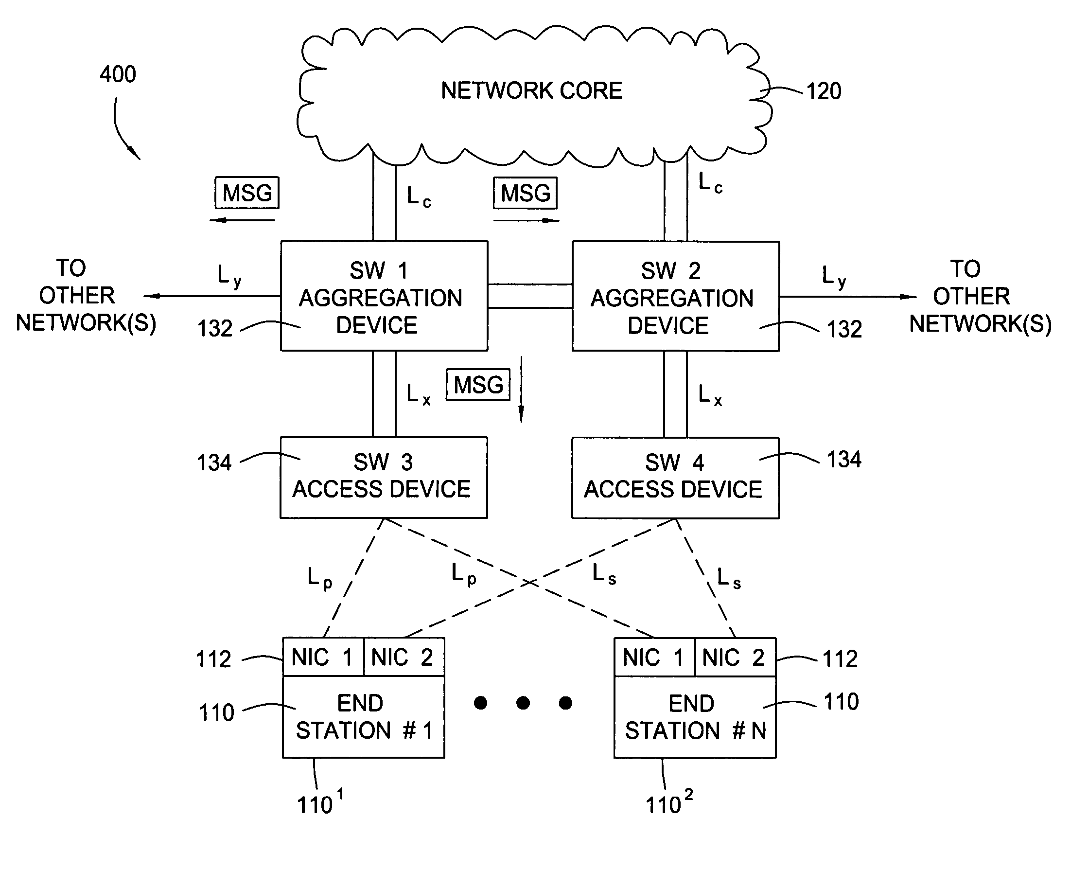
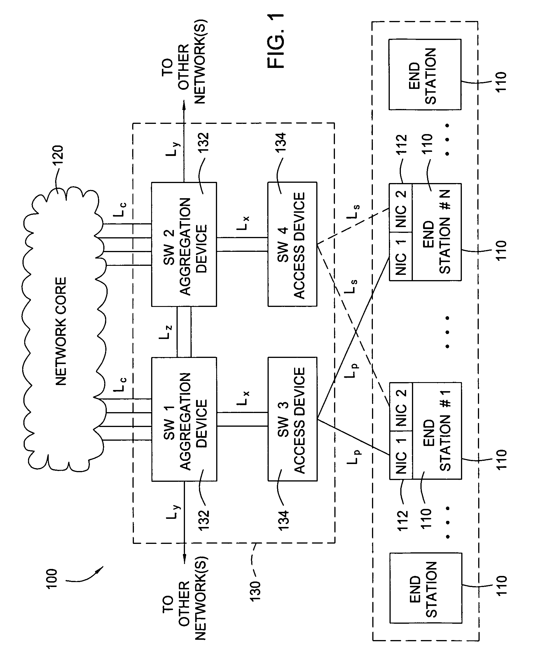
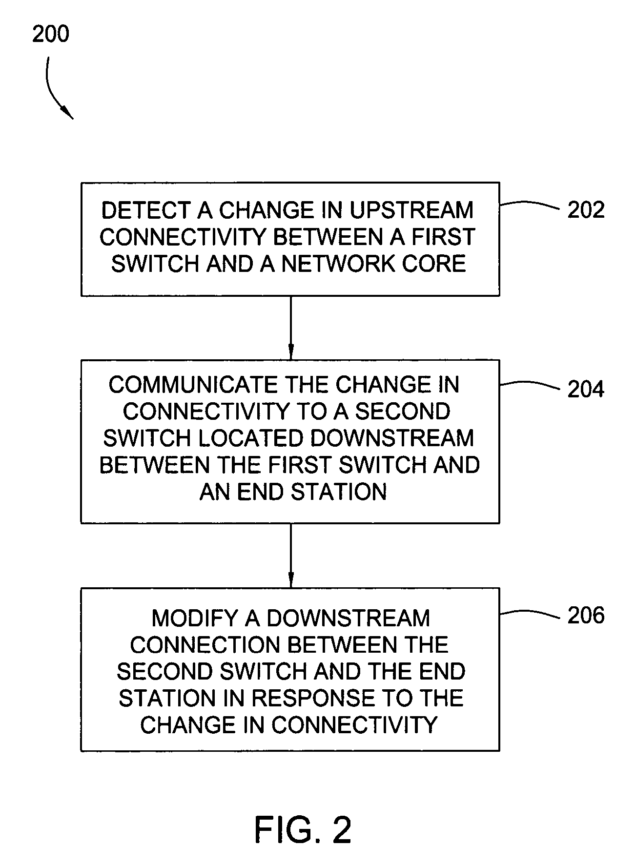
[0021]Embodiments of the present invention generally provide methods and apparatus for propagating changes in upstream connectivity downstream. For some embodiments, an upstream switch connected to a network core may detect a change in connectivity and, in response, send a message indicating the change to a downstream switch connected to an end station. In response to the message, the downstream switch may disable a link with end station. Disabling the link may cause the end station to promptly switch (fail over) to a different link, in an effort to establish an alternate path to the network. Further, by maintaining the link between the intermediate or downstream switch and the upstream device, network traffic routed through that switch need not be re-routed and the link can continue to carry traffic destined for other networks.

[0022]Methods and apparatus for managing a multilayer switching path are described. In the following description, numerous specific details are set forth in ...


PUM


Abstract

A method and apparatus that promote expedited fast link failover decisions by and end station with redundant multilayer switching paths to a network are disclosed. In response to detecting a change in connectivity with an upstream link to a network, an upstream switch may send a notification to an intermediate switch with a downstream link to the end station. In response to the notification, the intermediate switch may disable (“bring down”) the downstream link to the end station. Bringing the downstream link down in this manner may cause the end station to switch (“failover”) to a different downstream link, for example, allowing the end station to establish connectivity to the network via a redundant path.

Description

BACKGROUND OF THE INVENTION[0001]1. Field of the Invention[0002]The present invention generally relates to management of switched computer networks and, more particularly, to propagating detected changes in upstream connectivity to downstream devices.[0003]2. Description of the Related Art[0004]A computer network generally includes a number of devices, including switches, routers and hubs, connected so as to allow communication among the devices. The devices within a network may be generally categorized into two classes: end stations connected along the edge of a network and network devices. End stations typically include devices that primarily supply or consume information, such as workstations, desktop PCs, printers, servers, hosts, fax machines, and other such devices. Network devices typically include devices that primarily transfer information between other devices (e.g., between end stations and other network devices), such as gateways, switches, routers, and other such device...

Claims


Application Information

Patent Timeline
Patent Type & Authority Patents(United States)
IPC IPC(8): H04L1/00H04L12/26H04Q3/00H04L12/707G06F15/173H04L45/24
CPCH04L45/22H04Q3/0087
Inventor TIRUMALAI, GOKUL S.MITCHELL, ALBERT HYDE
Owner CISCO TECH INC
Learn More