Dual bladed surgical saw and method of use

a surgical saw and dual blade technology, applied in the field of surgical saws, can solve the problems of inability to make the sixty degree cuts required during austin bunionectomies, poor surgical procedure, and extreme accuracy, and achieve the effects of improving efficiency, improving accuracy and efficiency, and improving accuracy

Active Publication Date: 2014-11-18
MURPHY CHRISTOPHER B
View PDF8 Cites 3 Cited by
  • Summary
  • Abstract
  • Description
  • Claims
  • Application Information

AI Technical Summary

Benefits of technology

The present invention is a dual bladed surgical saw and method of use that can simultaneously make two cuts at a pre-determined angle. It has several design features, such as a saw body with two oscillators and a rotatable attachment between the two blade assemblies, which allow for precise and efficient surgical procedures. The angle between the cuts can also be varied prior to making the cuts. Additionally, it is inexpensive to produce and requires the use of commercially available components.

Problems solved by technology

This procedure is less than ideal, because it is time-consuming and not extremely accurate.
Thus, these would not be able to make the sixty degree cuts required during Austin bunionectomies, nor the ten to thirty degree angled cuts required for bone wedge removal, nor the other angled cuts required by other procedures.
While this design disclosed angular adjustability of the single blade, it did not disclose a single saw having two blades, nor adjustability of the angle between the two blades.
Thus, the Lee device would not serve to make the sixty degree cuts required during Austin bunionectomies, nor the ten to thirty degree angled cuts required for bone wedge removal, nor the other angled cuts required by other procedures.

Method used


Image

  • Dual bladed surgical saw and method of use
  • Dual bladed surgical saw and method of use
  • Dual bladed surgical saw and method of use

Examples


Embodiment Construction

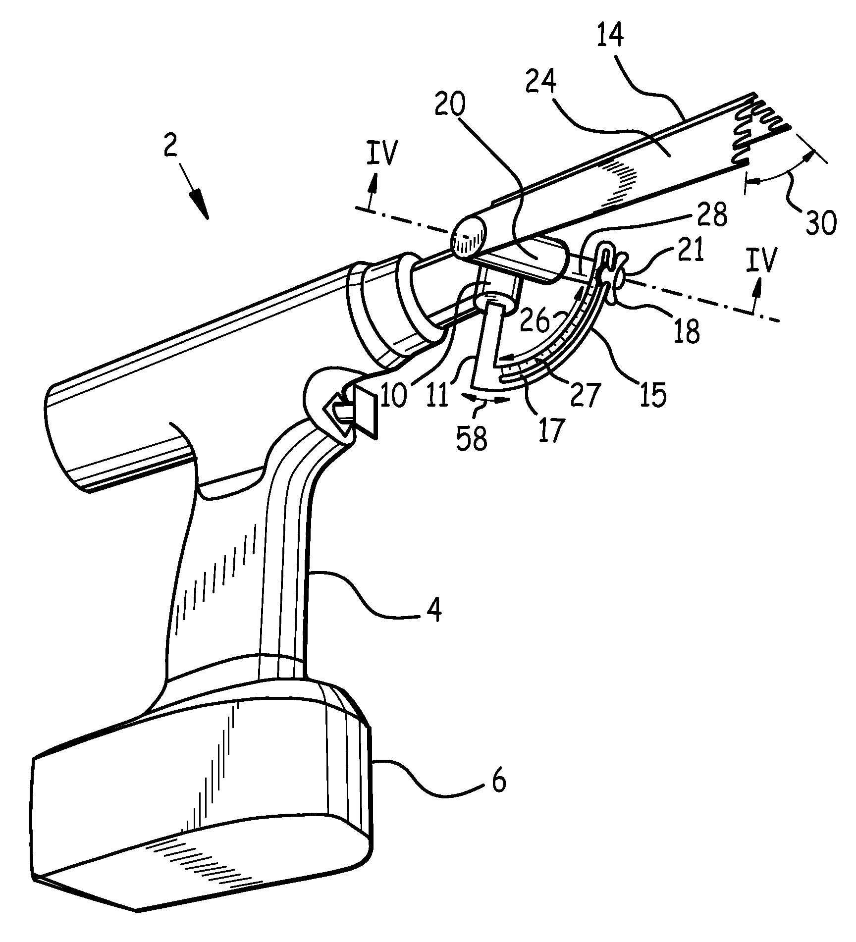
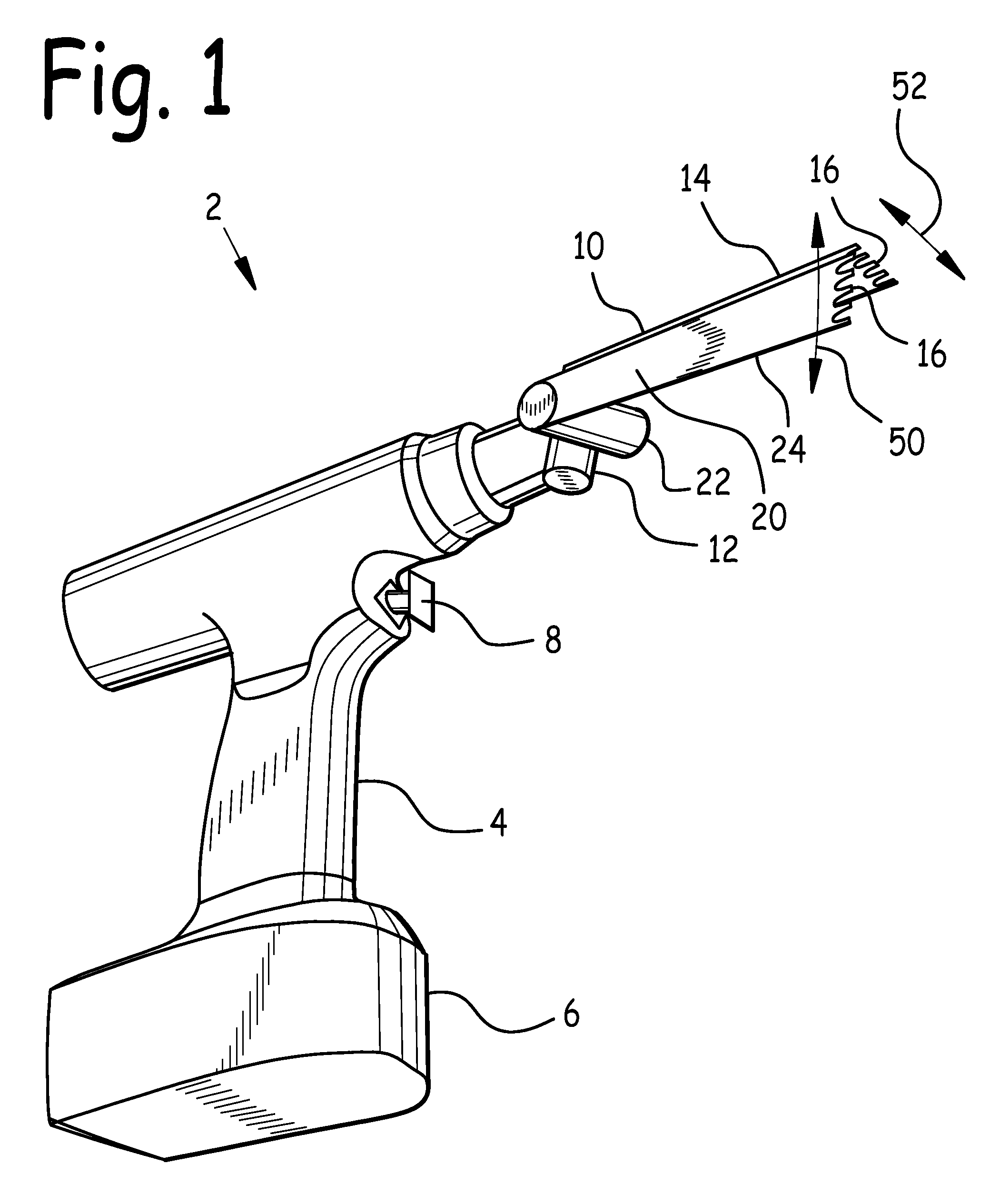
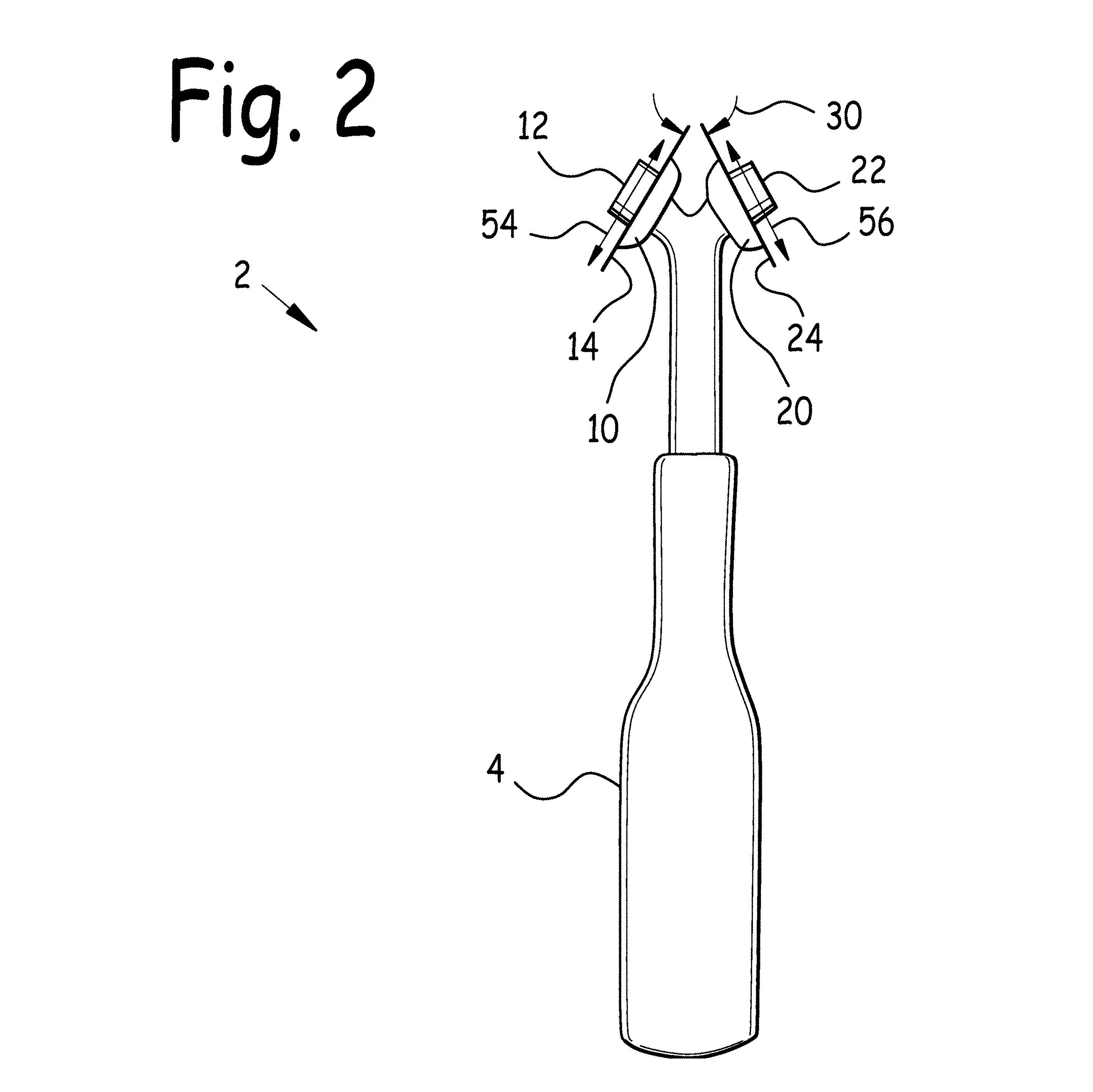
[0027]Referring now to FIG. 1, we observe a right side isometric view of dual bladed surgical saw 2. Dual bladed surgical saw 2 incorporates first blade assembly 10 and second blade assembly 20 attached to saw body 4. First blade assembly 10 includes first blade 14 attached to first oscillator 12 at one end, and has saw teeth 16 at the other. Second blade assembly 20 includes second blade 24 attached to second oscillator 22 at one end, and has saw teeth 16 at the other.

[0028]In the example illustrated in FIG. 1, saw body 4 is an electric saw body with battery 6 connected to first blade assembly 10 and second blade assembly 20 through switch 8. When switch 8 is closed, first oscillator 12 and second oscillator 22 oscillate, which in turn cause first blade 14 and second blade 24 to reciprocate as indicated by arrows 50 and 52. While some of the figures herein depict electric saw bodies 4, it is intended to fall within the scope of this disclosure that any appropriate saw body and osci...


PUM


Abstract

A dual bladed surgical saw and method of use. Two blade assemblies are attached to a saw body. Each blade assembly includes an oscillator driving a blade, and teeth on each blade. The blades are disposed at a pre-determined blade angle relative to each other, thus allowing two cuts to be made simultaneously and independently at the blade angle relative to each other. The blade assemblies may be rotatable relative to each other, which allows the pre-set blade angle to be varied appropriate to the procedure contemplated. One embodiment uses a slotted protractor bearing protractor indicia, and a threaded fastener to set the blade angle. Another embodiment uses shims between blade assembly arms to quickly and accurately set the blade angle. Method steps include pre-setting the blade angle, and making two cuts simultaneously at an angle relative to each other equal to the blade angle.

Description

BACKGROUND OF THE INVENTION[0001]1. Field of the Invention[0002]This invention relates to surgical saws, and in particular to a dual bladed surgical saw and method of use.[0003]2. Background of the Invention[0004]Certain surgical procedures require bone cuts at precise angles. For example, the most common bunion surgical procedure is the Austin bunionectomy, also known as the Chevron bunionectomy.[0005]The Austin bunionectomy procedure requires cutting a sixty degree angled cut into the first metatarsal head. The two resultant sections of the first metatarsal head are translated sideways, and then fixated. Fixation may be accomplished with a K-wire, pin, or other appropriate fixation device. Protruding sections of bone are cut off as appropriate, and a wedge may be removed from the first phalange as necessary. After the bones involved are aligned properly, they may be fixated with pins, screws, staples, etc., as appropriate.[0006]The optimal angle at which to make the Austin bunione...

Claims


Application Information

Patent Timeline
Patent Type & Authority Patents(United States)
IPC IPC(8): A61B17/00
CPCA61B17/141A61B17/148B26B3/04A61B17/142A61B17/1682
Inventor MURPHY, CHRISTOPHER, B.
Owner MURPHY CHRISTOPHER B
Why Eureka
Try Eureka