Magnetic resonance imaging method, system and computer-readable storage medium

a magnetic resonance imaging and computer-readable technology, applied in the field of magnetic resonance imaging methods, system and computer-readable storage media, can solve the problems of severe image artifacts, prone to artifacts in sequence construction, and “banding artifacts” to achieve the effect of more robustness and no loss in acquisition tim

Inactive Publication Date: 2014-11-18
SIEMENS HEALTHCARE GMBH
View PDF7 Cites 0 Cited by
  • Summary
  • Abstract
  • Description
  • Claims
  • Application Information

AI Technical Summary

Benefits of technology

[0013]An object of the present invention is to design the acquisition of an MR image with a magnetic resonance system to be more robust against interferences in the signal acquisition and image quality, using a pulse sequence that sets the magnetization vector in in a stable oscillation in the steady state under RF excitation pulses radiated at a time interval of time TR, without losses in the acquisition time.
[0015]By the minimization of the first moment according to the invention, the SSFP state can be largely maintained at least in the region of low k-space lines. The measurement data measured in this region are responsible for the contrast of the MR image ultimately reconstructed from all measurement data. Due to movement in the high k-space positions, the effect of dephased spin isochromats—thus distorted SSFP states—is therefore of lesser importance to the reconstructed MR image. A marked improvement in the image quality of the reconstructed MR images is thus achieved via the method according to the invention due to the reduction of artifacts and the maintenance of the signal strength without having to extend the total measurement time, which would have a negative effect on the profitability [cost-effectiveness] of the method.

Problems solved by technology

Unfortunately, this sequence construction is prone to artifacts given the use of echo times that are longer than has previously been typical.
If this gradient area described by the zeroth moment is not zero at the point in time of the repetition time TR, this leads to severe image artifacts, known as “banding artifacts”.

Method used


Image

  • Magnetic resonance imaging method, system and computer-readable storage medium
  • Magnetic resonance imaging method, system and computer-readable storage medium
  • Magnetic resonance imaging method, system and computer-readable storage medium

Examples


Embodiment Construction

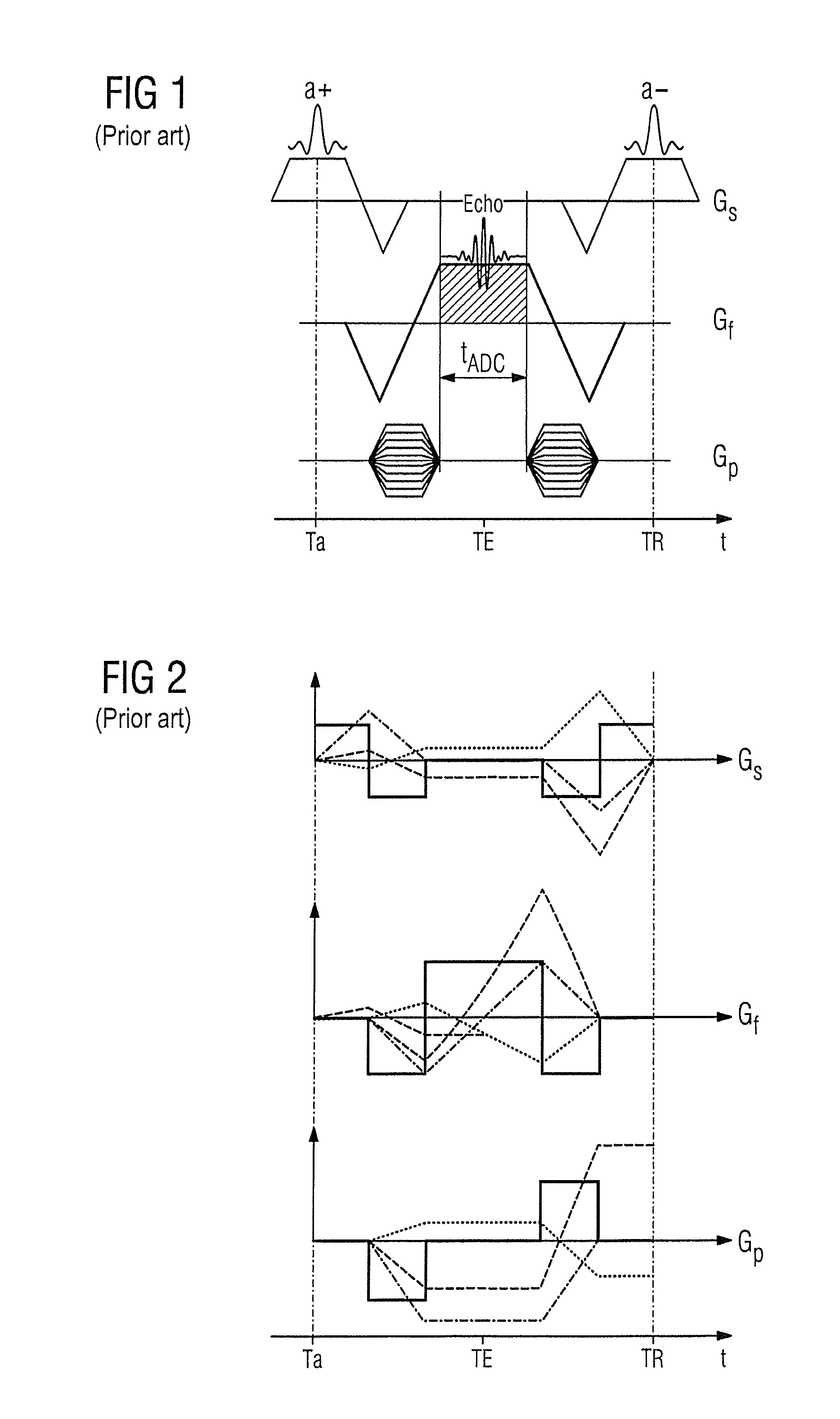
[0024]FIG. 1 schematically shows a known balanced trueFISP sequence. Time is indicated on the axis from left to right. At a point in time Ta an excitation / refocusing pulse α+ is radiated, wherein a slice selection gradient Gs has already been switched in the slice direction to select a slice to be measured. At a later point in time TE (the echo time) after the excitation / refocusing pulse α+, an echo signal “echo” forms that is read out during the readout time period tADC while a readout gradient Gf is switched in the frequency coding direction. At another later point in time TR that corresponds to double the echo time TE after the excitation / refocusing pulse α+, an excitation / refocusing pulse α− is radiated again, with a phase coding gradient Gp being activated between the excitation / refocusing pulse α+ and the excitation / refocusing pulse α− in order to complete the spatial coding. During the course of such a trueFISP sequence, alternating excitation / refocusing pulse α+ and α− are r...


PUM


Abstract

In a magnetic resonance method and system to acquire an MR image using a pulse sequence that sets the magnetization vector in the steady state into a stable oscillation under RF excitation pulses radiated at a time interval of time TR, the phase coding gradients for coding a k-space line in k-space of the pulse sequence (which k-space corresponds to the desired MR image) are switched such that the first moment of the phase coding gradient is minimal at the point in time of the radiation of an RF excitation pulse without the repetition time TR being extended relative to pulse sequences with unminimized phase coding gradients.

Description

BACKGROUND OF THE INVENTION[0001]1. Field of the Invention[0002]The invention concerns a method to acquire an MR image with a magnetic resonance system by means of a pulse sequence, a corresponding magnetic resonance system, and a corresponding electronically readable data storage medium.[0003]2. Description of the Prior Art[0004]Magnetic resonance (MR) is a known modality with which images of the inside of an examination subject can be generated. Expressed in simple terms, the examination subject is positioned in a strong, static, homogeneous basic magnetic field B0 (field strengths from 0.2 to 7 Tesla or more) in a magnetic resonance apparatus so that nuclear spins in the subject orient along the basic magnetic field. For spatial coding of the measurement data, rapidly switched gradient fields are superimposed on the basic magnetic field. To trigger nuclear magnetic resonances, radio-frequency excitation pulses (RF pulses) are radiated into the examination subject by means of at l...

Claims


Application Information

Patent Timeline
Patent Type & Authority Patents(United States)
IPC IPC(8): G01R33/561G01R33/54G01R33/565G01R33/34
CPCG01R33/56509G01R33/5614
Inventor DEIMLING, MICHAEL
Owner SIEMENS HEALTHCARE GMBH
Why Eureka
Try Eureka