Power source for electric arc welding

a technology of power source and electric arc welding, which is applied in the direction of arc welding apparatus, welding apparatus, manufacturing tools, etc., can solve the problems of heat loss, increased primary current and more losses, and reduced efficiency, so as to reduce component sizes, prevent losses, and reduce magnetic losses

Active Publication Date: 2006-01-19
LINCOLN GLOBAL INC
View PDF99 Cites 57 Cited by
  • Summary
  • Abstract
  • Description
  • Claims
  • Application Information

AI Technical Summary

Benefits of technology

[0023] Another object of the present invention is the provision of a power source and method, as defined above, which power source and method uses a high switching frequency above 18 kHz and about 100 kHZ with a fixed duty cycle to prevent losses.
[0024] Yet another ob

Problems solved by technology

Lower duty cycles resulted in higher primary currents and more losses.
Using a power source where the final stage is a regulated single stage inverter resulted in heat losses, lower efficiency, high cost and increased compo

Method used


Image

  • Power source for electric arc welding
  • Power source for electric arc welding
  • Power source for electric arc welding

Examples


Embodiment Construction

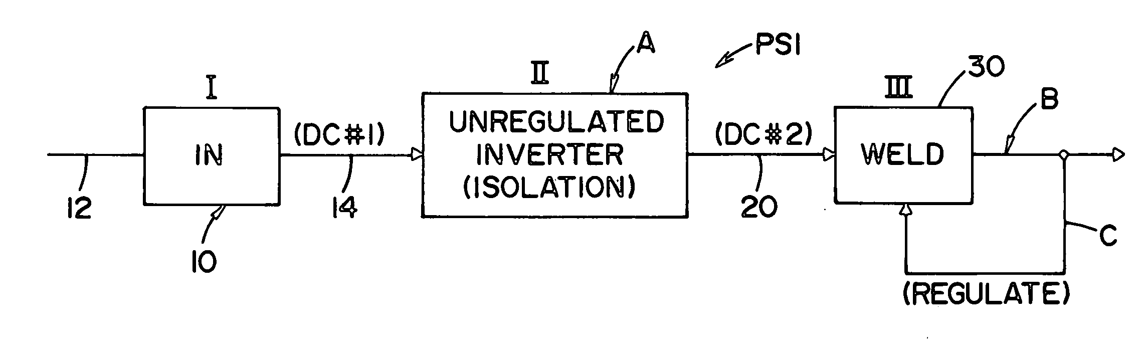
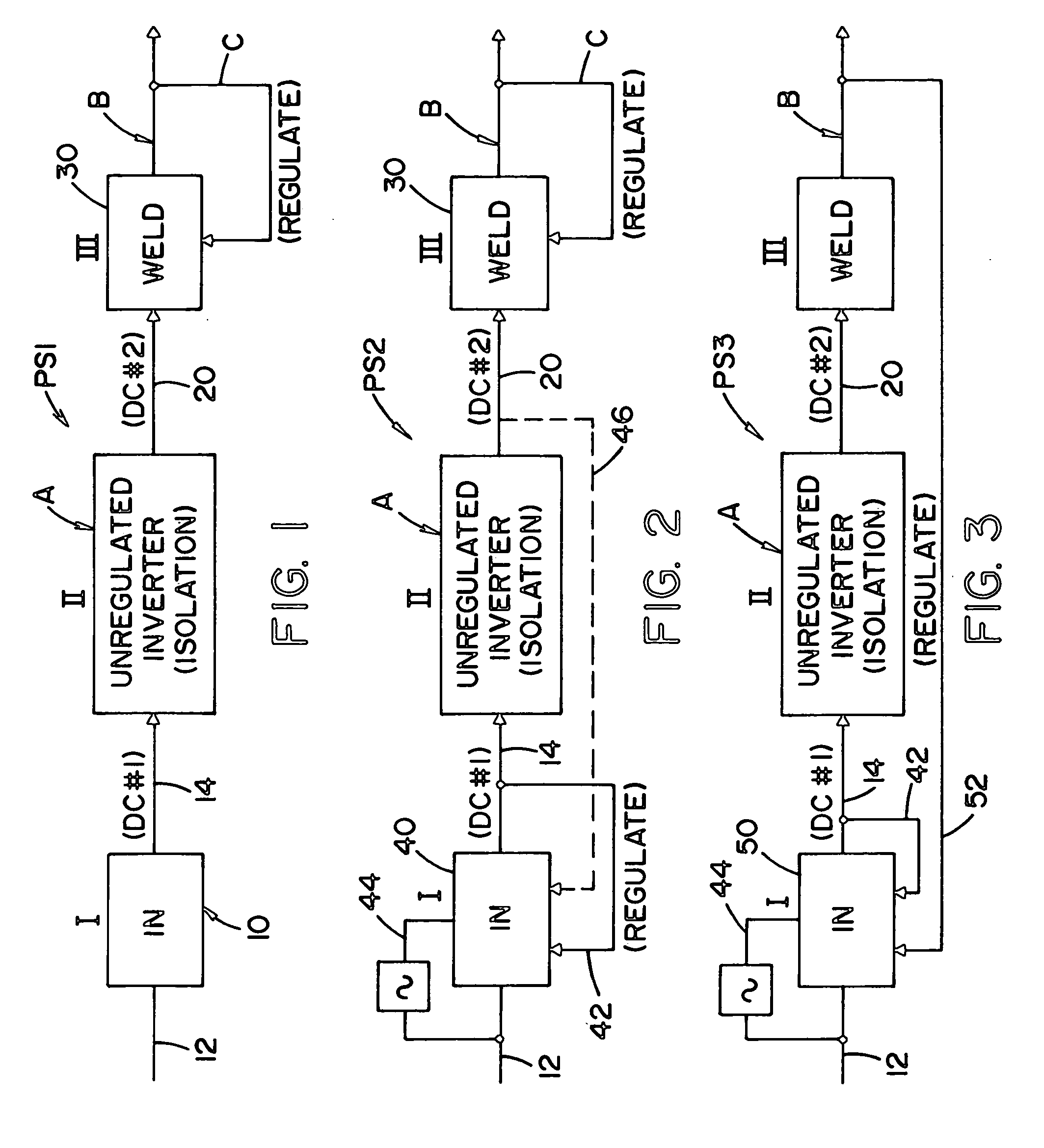
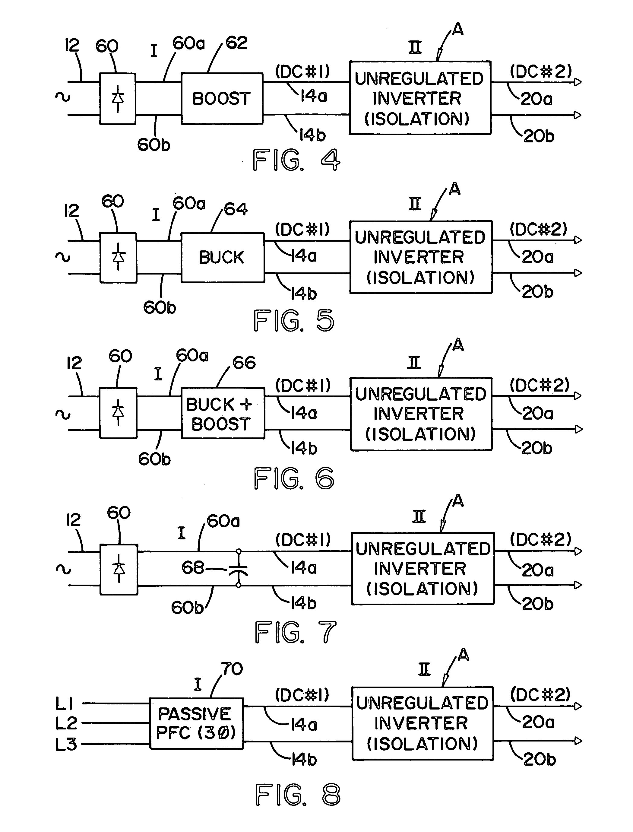
[0039] The present invention relates to a three stage power source for use in electric arc welding. Of course, the concept of welding also encompasses the related technology of plasma cutting. The invention has an input stage for converting an AC signal into a first DC output bus. This output bus has a fixed voltage level in accordance with the preferred embodiment of the invention and is directed to the input of a novel second stage used in the welding technology and best shown in FIG. 16. This novel second stage is an unregulated inverter which includes an isolation feature and has a second DC output or second DC bus which is proportional to the DC input bus. The level relationship is fixed by the construction of the unregulated inverter. The unregulated inverter has a switching network wherein the switches are operated at a high switching frequency greater than 18 kHz and preferably about 100 kHz. The switching frequency of the switch network in the unregulated inverter forming t...


PUM

PropertyMeasurementUnit
Fractionaaaaaaaaaa
Frequencyaaaaaaaaaa
Poweraaaaaaaaaa

Abstract

A power source for an electric arc welding process, wherein the power source comprises an input stage having an AC input and a first DC output signal; a second stage in the form of an unregulated DC to DC converter having an input connected to the first DC output signal and an output in the form of a second DC output signal electrically isolated from the first DC output signal and with a magnitude of a given ratio to the first DC output signal; and, a third stage to convert the second DC output signal to a welding output for the welding process.

Description

[0001] The invention relates to the field of electric arc welding and more particularly to a power source for such welding and the method implemented by use of the novel power source. INCORPORATION BY REFERENCE AND BACKGROUND OF INVENTION [0002] Electric arc welding involves the passing of an AC or DC current between a metal electrode and a workpiece where the metal electrode is normally a cored metal wire or solid metal wire. A power source is used to create a given current pattern and / or polarity between the advancing electrode wire and workpiece so that the arc will melt the end of the advancing welding wire and deposit the molten metal on the workpiece. Although various converter technologies are used for power sources, the most effective is an inverter based power source where a switching network includes switches operated at high frequency to create the desired waveform or current level for the welding process. An inverter type power source is discussed in Blankenship U.S. Pat...

Claims


Application Information

Patent Timeline
IPC IPC(8): B23K9/10
CPCB23K9/1006B23K9/06B23K9/093B23K9/1043B23K9/09
Inventor DANIEL, JOSEPH A.KOOKEN, TODD E.LUO, LIFENG
Owner LINCOLN GLOBAL INC
Why Eureka
Try Eureka