Ultrasonic waterjet apparatus

a waterjet and ultrasonic technology, applied in the direction of cleaning using liquids, combustion types, borehole/well accessories, etc., can solve the problems of increasing costs, nozzles, water lines and fittings are bulky, and the effect of increasing the capacity of the apparatus to clean, cut, deburr, and decoa

Active Publication Date: 2009-09-29
PRATT & WHITNEY MILLTARY AFTERMARKET SERVICES
View PDF11 Cites 65 Cited by
  • Summary
  • Abstract
  • Description
  • Claims
  • Application Information

AI Technical Summary

Benefits of technology

[0019]An advantage of the present invention is that the ultrasonic waterjet apparatus generates a much higher effective impact pressure than continuous-flow waterjets, thus augmenting the apparatus' capacity to clean, cut, deburr, de-coat and break. By pulsating the waterjet, a train of mini slugs of water impact the target surface, each slug imparting a waterhammer pressure. For a given pressure source, the waterhammer pressure is much higher than the stagnation pressure of a continuous-flow waterjet. Therefore, the ultrasonic waterjet apparatus can operate with a much lower source pressure in order to cut and deburr, to clean and remove coatings, and to break rocks and rock-like substances. The ultrasonic waterjet apparatus is thus more efficient, more robust, and less expensive to construct and utilize than conventional continuous-flow waterjet systems.
[0020]Another aspect of the present invention provides an ultrasonic nozzle for use in an ultrasonic waterjet apparatus. The ultrasonic nozzle includes a transducer for converting high-frequency electrical pulses into mechanical vibrations that pulsate a waterjet flowing through the nozzle, creating a waterjet of pulsed slugs of water, each slug of water capable of imparting a waterhammer pressure on a target surface. The nozzle has a rotating nozzle head or multiple exit orifices for cleaning or de-coating large surfaces.
[0021]Another aspect of the present invention provides an ultrasonic nozzle for use in an ultrasonic waterjet apparatus including a transducer for converting high-frequency electrical pulses into mechanical vibrations that pulsate a waterjet flowing through the nozzle, creating a waterjet of pulsed slugs of water, each slug of water capable of imparting a waterhammer pressure on a target surface, the transducer having a microtip with a seal for isolating the transducer from the waterjet, the seal being located at a nodal plane where the amplitude of standing waves set up along the microtip is zero.
[0022]Another aspect of the present invention provides related methods of cutting, cleaning, deburring, de-coating and breaking rock-like materials with an ultrasonically pulsed waterjet. The method includes the steps of forcing a high-pressure continuous-flow waterjet through a nozzle; generating high-frequency electrical pulses; transmitting the high-frequency electrical pulses to a transducer; transducing the high-frequency electrical pulses into mechanical vibrations; pulsating the high-pressure continuous flow waterjet to transform it into a pulsated waterjet of discrete water slugs, each water slug capable of imparting a waterhammer pressure on a target surface; and directing the pulsated waterjet onto a target material. Depending on the desired application, the ultrasonically pulsed waterjet can be used to cut, clean, de-burr, de-coat or break.
[0023]Where the application is cleaning or de-coating a large surface, the ultrasonic waterjet apparatus advantageously includes a nozzle with multiple exit orifices or with a rotating nozzle head.

Problems solved by technology

Continuous-flow waterjet technology, of which the foregoing are examples, suffers from certain drawbacks which render continuous-flow waterjet systems expensive and cumbersome.
Consequently, the nozzle, water lines and fittings are bulky, heavy and expensive.
To deliver an ultra-high-pressure waterjet, an expensive ultra-high-pressure water pump is required, which further increases costs both in terms of the capital cost of such a pump and the energy costs associated with running such a pump.

Method used


Image

  • Ultrasonic waterjet apparatus
  • Ultrasonic waterjet apparatus
  • Ultrasonic waterjet apparatus

Examples


second embodiment

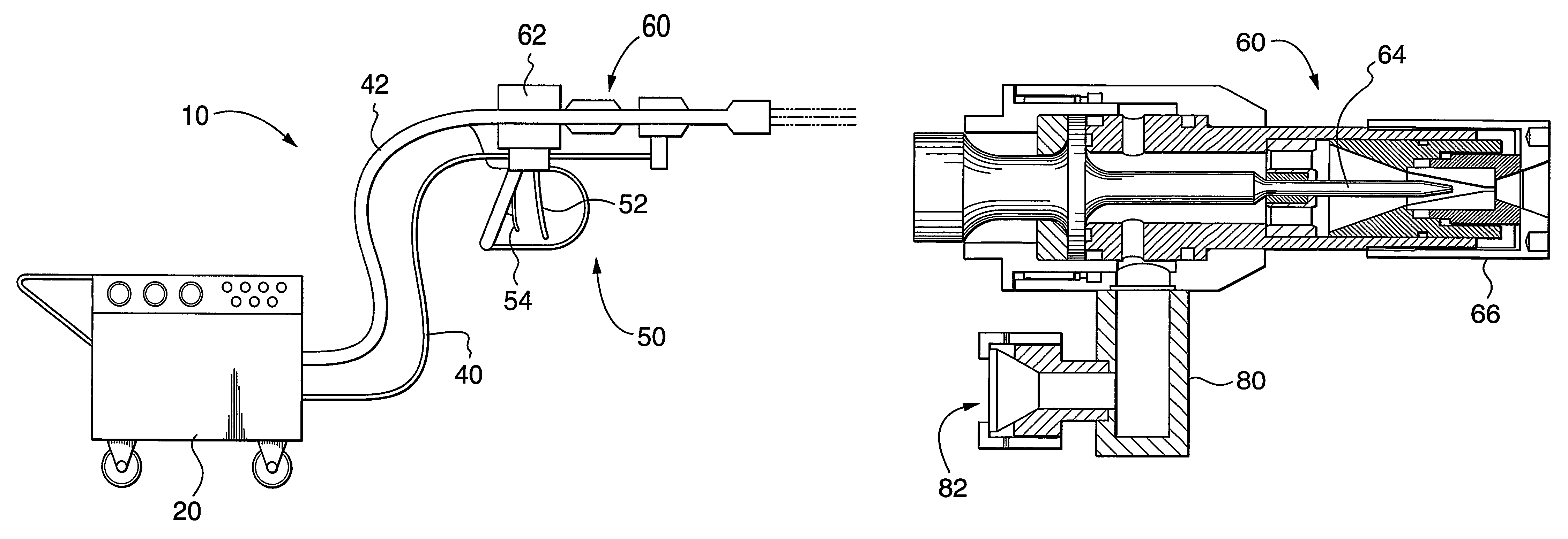
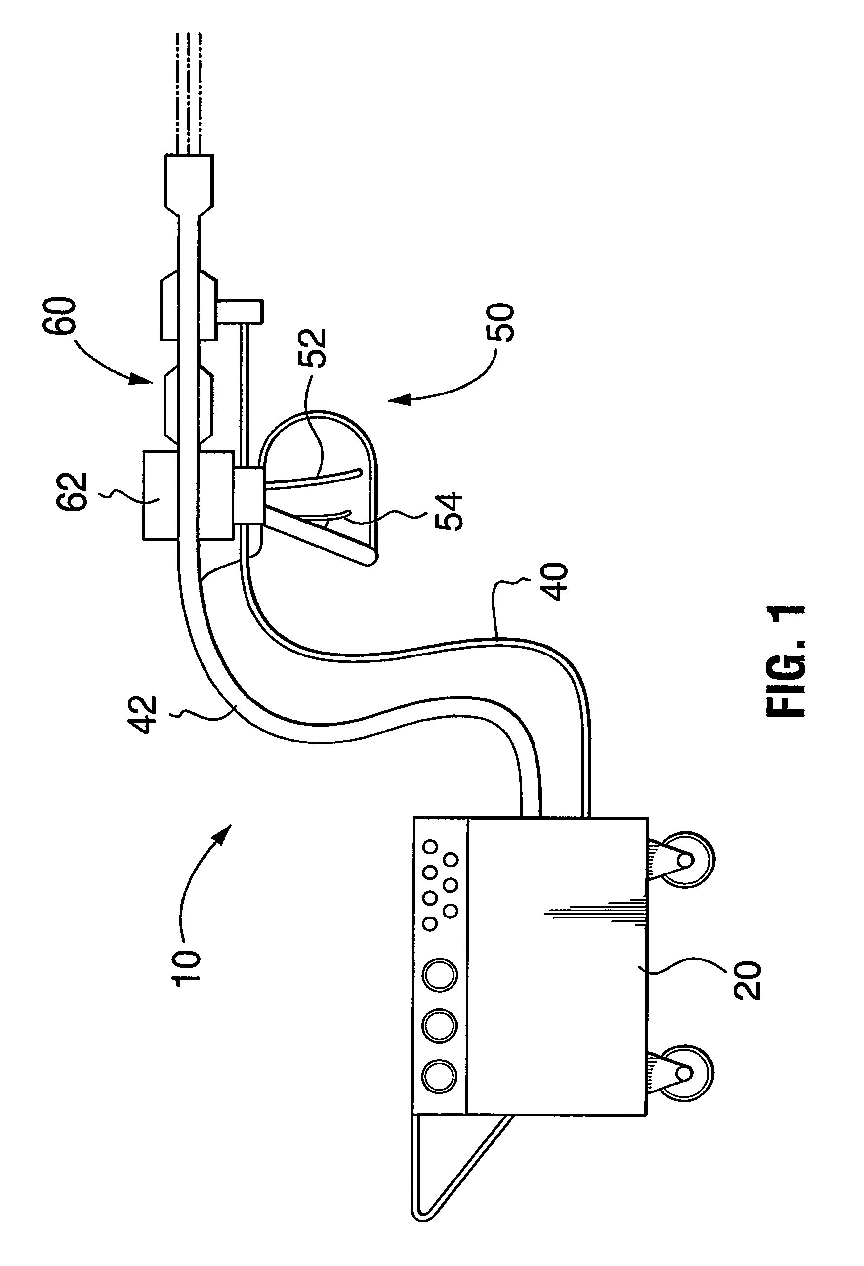
[0059]As shown in FIG. 7, the ultrasonic nozzle 60 has a single orifice 61. A single orifice is useful for many applications such as cutting and deburring various materials as well as breaking rock-like materials. However, for applications such as cleaning or de-coating large surface areas, a single orifice only removes a narrow swath per pass. Therefore, for applications such as cleaning and removing coatings such as paint, enamel, or rust, it is useful to provide a second embodiment in which the ultrasonic nozzle has a plurality of orifices. An ultrasonic nozzle 60 with three orifices 61a is shown in FIG. 11. The microtip has three prongs for modulating the waterjet as it is forced through the three parallel exit orifices. The triple-orifice nozzle of FIG. 11 is thus able to clean or de-coat a wider swath than a single-orifice nozzle. As shown in FIG. 11, a nut 60a secures the multiple-orifice nozzle to a housing 60b. FIG. 11 shows how the microtip 64 culminates in three prongs 64...

third embodiment

[0060]In a third embodiment, which is illustrated in FIG. 12, the ultrasonic nozzle 60 has a rotating nozzle head 90 which permits the ultrasonic nozzle 60 to efficiently clean or de-coat a large surface area. The rotating nozzle head 90 is self-rotating because water is bled off into two outer jets 92. The bled-off water generates torque which causes the outer jets 92 to rotate, which, in turn, cause the rotating nozzle head 90 to rotate. In this embodiment, the bulk of the waterjet is forced through one or two angled exit orifices 91. Depending on the material to be cleaned, the outer jets may or may not contribute to the cleaning process. An acoustically matching swivel 94 is interposed between the transducer and the rotating nozzle head. The swivel 94 is designed to not only withstand the pressure but also acoustically match the rest of the system to achieve resonance. The swivel 94 may or may not have a speed control mechanism, such as a rotational damper, for limiting the angu...


PUM


Abstract

An ultrasonic waterjet apparatus (10) has a mobile generator module (20) and a high-pressure water hose (40) for delivering high-pressure water from the mobile generator module (20) to a hand-held gun (50) with a trigger and an ultrasonic nozzle (60). An ultrasonic generator in the mobile generator module (20) transmits high-frequency electrical pulses to a piezoelectric or magnetostrictive transducer (62) which vibrates to modulate a high-pressure waterjet flowing through the nozzle (60). The waterjet exiting the ultrasonic nozzle (60) is pulsed into mini slugs of water, each of which imparts a waterhammer pressure on a target surface. The ultrasonic waterjet apparatus (10) may be used to cut and de-burr materials, to clean and de-coat surfaces, and to break rocks. The ultrasonic waterjet apparatus (10) performs these tasks with much greater efficiency than conventional continuous-flow waterjet systems because of the repetitive waterhammer effect. A nozzle with multiple exit orifices or a rotating nozzle (76) may be provided in lieu of a nozzle with a single exit orifice to render cleaning and de-coating large surfaces more efficient. A water dump valve (27) and controlling solenoid are located in the mobile generator module (20) rather than the gun (50) to make the gun lighter and more ergonomic.

Description

[0001]This application is a 35 U.S.C. 371 of PCT / CA03 / 01683 filed Nov. 3, 2003.TECHNICAL FIELD[0002]The present invention relates, in general, to high-pressure waterjets for cleaning and cutting and, in particular, to high-frequency modulated waterjets.BACKGROUND OF THE INVENTION[0003]Continuous-flow high-pressure waterjets are well known in the art for cleaning and cutting applications. Depending on the particular application, the water pressure required to produce a high-pressure waterjet may be in the order of a few thousand pounds per square inch (psi) for fairly straightforward cleaning tasks to tens of thousands of pounds per square inch for cutting and removing hardened coatings.[0004]Examples of continuous-flow, high-pressure waterjet systems for cutting and cleaning are disclosed in U.S. Pat. Nos. 4,787,178 (Morgan et al.), 4,966,059 (Landeck), 6,533,640 (Nopwaskey et al.), 5,584,016 (Varghese et al.), 5,778,713 (Butler et al.), 6,021,699 (Caspar), 6,126,524 (Shepherd) and ...

Claims


Application Information

Patent Timeline
Patent Type & Authority Patents(United States)
IPC IPC(8): B05B1/08B05B3/02B05B12/06B05B15/00B08B3/02
CPCB26F3/004B05B1/083B05B12/06B05B17/0623B08B3/026B05B3/02B08B2203/0288B26D5/00Y10S239/04
Inventor VIJAY, MOHAN M.YAN, WENZHUOTIEU, ANDREWREN, BAOLIN
Owner PRATT & WHITNEY MILLTARY AFTERMARKET SERVICES
Why Eureka
Try Eureka