Friction stir welding tool cleaning method and apparatus

a technology of cleaning method and apparatus, which is applied in the direction of auxillary welding device, soldering apparatus, cleaning using liquids, etc., can solve the problems of pin tool plunge, uncertainty about the quality of welds, and parts being destroyed, so as to reduce inspection cycles, reduce costs, and facilitate use

Active Publication Date: 2007-12-13
THE BOEING CO
View PDF7 Cites 33 Cited by
  • Summary
  • Abstract
  • Description
  • Claims
  • Application Information

AI Technical Summary

Benefits of technology

[0007]The invention satisfies this need for an improved friction stir welding tool cleaning method and apparatus, as well as provides a unique and advantageous friction stir welding tool cleaning method and apparatus. None of the known cleaning methods and devices provides all of the numerous advantages of the invention. The invention is directed to a unique and nonobvious friction stir welding tool cleaning method and apparatus that can be used with fixed and retractable pin tools used in the friction stir welding process to remove weld process residue material from the friction stir welding tool. Unlike known cleaning methods and devices, the friction stir welding tool cleaning method and apparatus of the invention provides the following advantages: it is easy to use; it is less expensive than chemically removing the residue; it is less tedious than manually removing the residue; it provides improved cleaning of friction stir welding tools allowing for reduced inspection cycles for damaged and embedded materials; it can significantly reduce the time to clean the friction stir welding tool of weld process residue material that gets pushed into pin and shoulder areas; it provides a method and apparatus that enhances the inspection process, eliminates or minimizes tool changes that are not required, and allows for precise load and torque measurements critical for adaptive and load control modes; and it provides a method and apparatus that improves cycle time and reduces the cost of friction stir welding.

Problems solved by technology

When using a retractable pin tool during welding, excess weld process residue material builds up between the shoulder's inside diameter and the pin tool's outside diameter and can inhibit the load sensed by a system controller, such as a force control device, possibly causing an over plunge of the pin tool due to false readings in the axial direction.
False readings can result in uncertainty about the quality of the weld.
In addition, if more load is applied due to a false reading, the tools can over penetrate the surface and dig into the welding components, thus destroying the part.
This loading effect can also inhibit correct torque readings making adaptive control much more difficult.
When using a fixed pin tool during welding, weld process residue build-up limits the optical inspection of tools and may inhibit a decision to continue or to limit use of that tool.
If tools are checked electronically or with a laser system, the residue build-up may imply that the tool integrity is unacceptable when, in fact, a tool change may not be required and the necessary action would be to clean the tool before the inspection process.
However, this method is time consuming and tedious, and it may take hours to thoroughly clean the tools.
In addition, this method may not remove all of the residue material on the tools.
However, this method is also time consuming and can take up to 24 hours to complete.
However, this method can be risky and damage to the tool can occur because the high temperature cannot be adequately controlled.
For example, if the tools are heat treated at too high a temperature, the heat may anneal the material and alter the heat treatment property of the tools, and then the tools may be damaged and cannot be used in the friction stir welding process.

Method used


Image

  • Friction stir welding tool cleaning method and apparatus
  • Friction stir welding tool cleaning method and apparatus
  • Friction stir welding tool cleaning method and apparatus

Examples


Embodiment Construction

[0028]The invention now will be described more fully hereinafter with reference to the accompanying drawings, in which some, but not all embodiments of the invention are shown. Indeed, this invention may be embodied in several different forms and should not be construed as limited to the embodiments set forth herein; rather, these embodiments are provided so that this disclosure will be thorough and complete, and will fully convey the scope of the invention to those skilled in the art. Like numbers refer to like elements throughout.

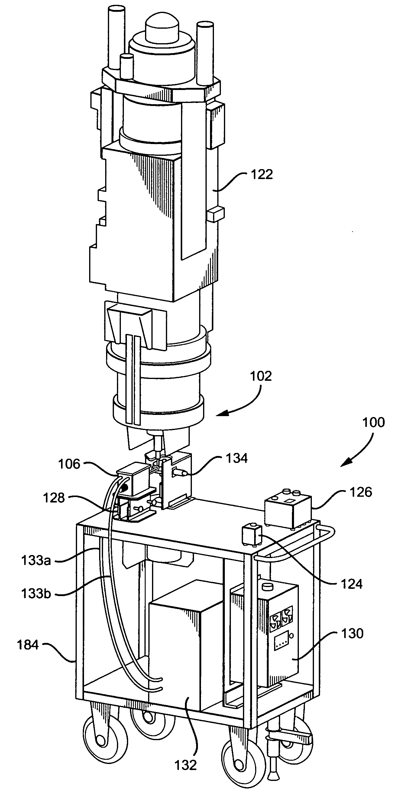
[0029]Referring now to the drawings, and in particular, to FIG. 2, there is shown an apparatus and system 100 for cleaning friction stir welding tools. The apparatus and system integrate a solid state, medium frequency, induction heating component with a powered rotating tool cleaner component, a temperature indicator component, and a separate controller component. The apparatus 100 is preferably used with a conventional friction stir welding machine 102....


PUM

PropertyMeasurementUnit
timeaaaaaaaaaa
lengthaaaaaaaaaa
temperatureaaaaaaaaaa

Abstract

The invention is directed to a friction stir welding tool cleaning method and apparatus for fixed and retractable pin tools. The method and apparatus use a heating component, a temperature indicator component, a controller component, and a rotatable tool cleaner component for cleaning fixed pin tools. An additional bore cleaner component is used for cleaning retractable pin tools. Heat is applied to a friction stir welding tool having a surface with weld process residue material until the process residue material is sufficiently plasticized, and then the tool cleaner component is applied to the heated tool to remove the plasticized residue on the pin and shoulder surfaces of the tool, and for retractable pin tools, the bore cleaner component is applied to the heated tool to remove the plasticized residue in the tool bore.

Description

BACKGROUND OF THE INVENTION[0001]1) Field of the Invention[0002]The invention relates to friction stir welding, and more specifically, to a friction stir welding tool cleaning method and apparatus.[0003]2) Description of Related Art[0004]Friction stir welding is a process that combines extruding and forging and is specifically designed for welding aluminum extrusions and other metal extrusions. Friction stir welding is a process in which a rotating cylindrical tool, that includes a threaded pin or probe attached to a shoulder that may be scrolled, concave or of another suitable configuration, is slowly plunged into or through a workpiece in order to join multiple structural members of the workpiece in a solid state or to repair cracks in the workpiece. FIG. 1 shows a conventional friction stir welding device. As shown in FIG. 1, the tool 10 includes the pin 12 that typically extends from the shoulder 14, which can be concave, flat or otherwise contoured. The shoulder 14 is urged aga...

Claims


Application Information

Patent Timeline
Patent Type & Authority Applications(United States)
IPC IPC(8): B23K20/12B23K37/00
CPCB23K20/26B23K20/1225B08B1/04B08B7/04
Inventor MATLACK, MICHAEL P.BURTON, KURT A.
Owner THE BOEING CO
Why Eureka
Try Eureka