This helps you quickly interpret patents by identifying the three key elements:
Problems solved by technology
Method used
Benefits of technology
Benefits of technology
[0006]The present invention is directed to a knife, or cutter, that is operative to pierce and cut a sheet of material, such as plastic material. The present invention is particularly applicable to cutting plastic sheeting of a temporary dust partition to which a zippered opening has been applied. In this manner, zipper installation can be established in a manner that alleviates the problems associated with the non-uniform plastic flap that would otherwise remain between the left and right flanges of the zipper.
[0007]In particular, an embodiment of the present invention includes two cutting blades that are positioned in parallel on left and right portions of the cutter. In this manner, when force is applied to the handle, two parallel cuts are made in the plastic, side-by-side, in order to cut a swath of plastic material of a width that is determined by the distance between the blades. Accordingly, the cutter of the present invention is especially amenable to use during zipper installation as described above, for removing a large portion of the material sheeting between the flanges of the installed zipper, thus providing a clean, uniform cut, and reducing the possibility of a remaining flap interfering with the operation of the zipper.
Problems solved by technology
The flap is usually non-uniform in width, as the knife, when cutting, can waver between the left and right sides of the opening, leaving a unsightly seam.
In addition, the flap can interfere with the operation of the zipper, as it can become lodged, or otherwise snag, in the teeth of the zipper during closure.
A box cutter also has an exposed razor blade that can be dangerous to operate.
Method used
Image
Click on the blue label to locate the original text in one second.
Reading with bidirectional positioning of images and text.
Examples
Embodiment Construction
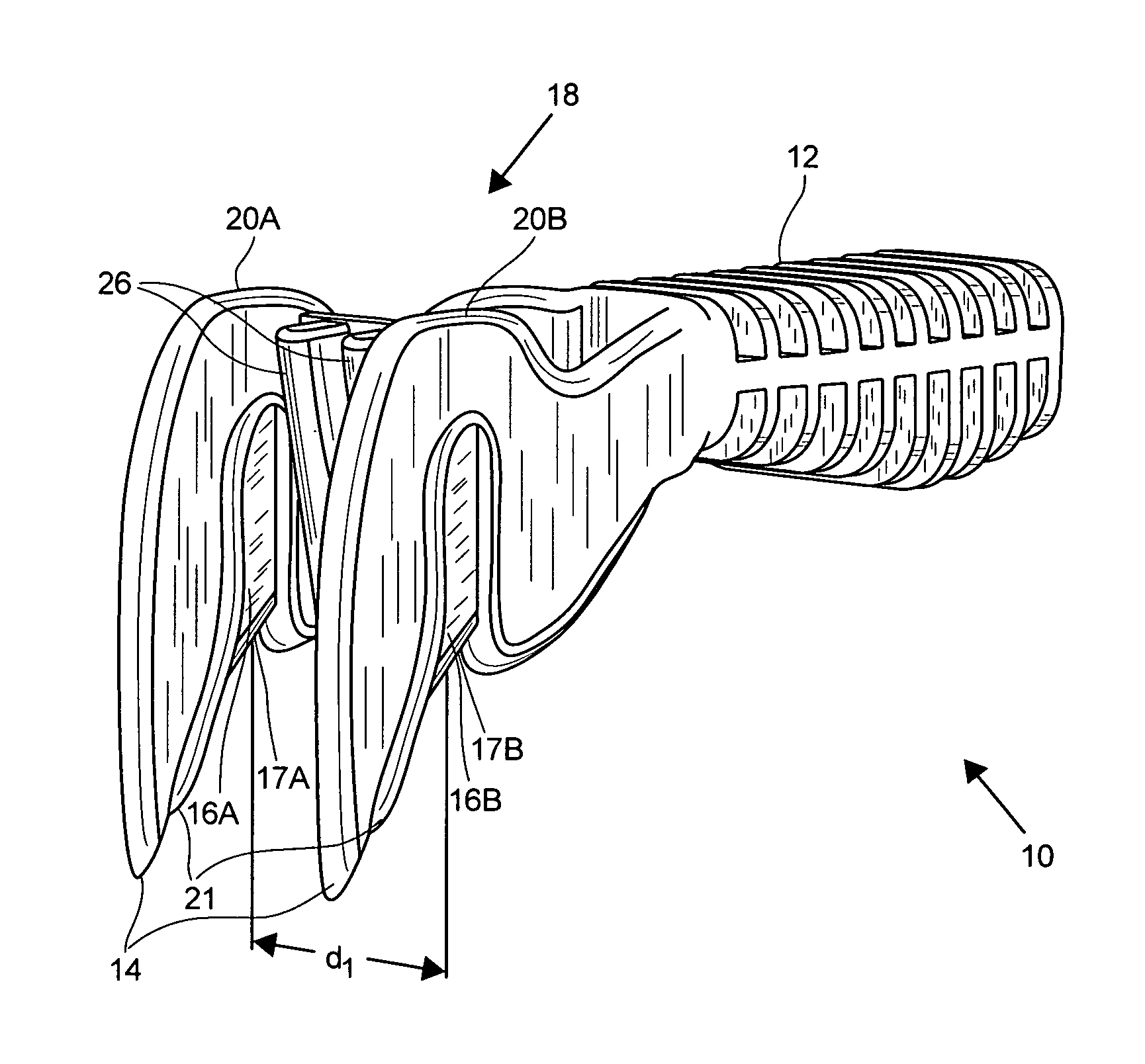
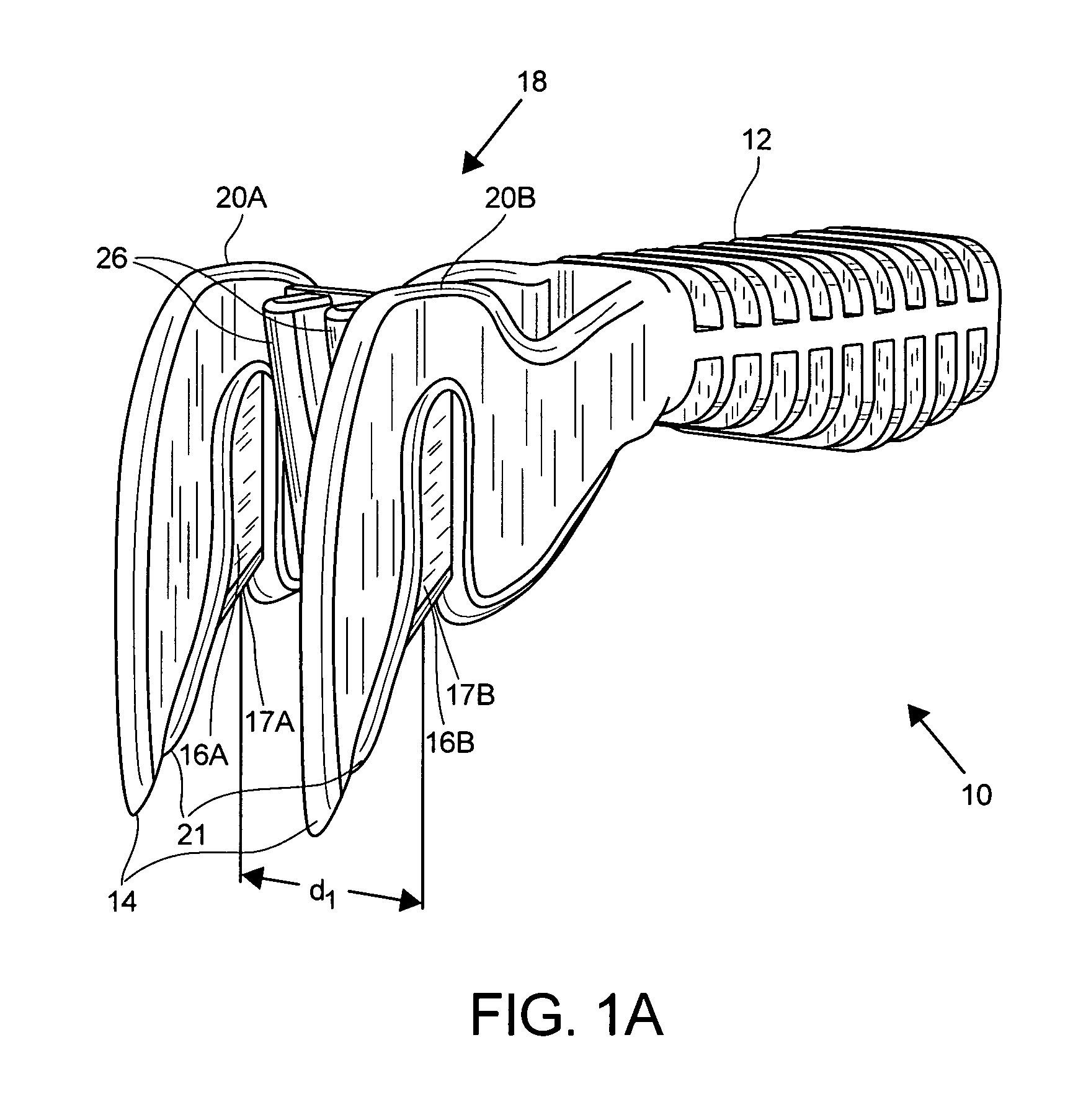
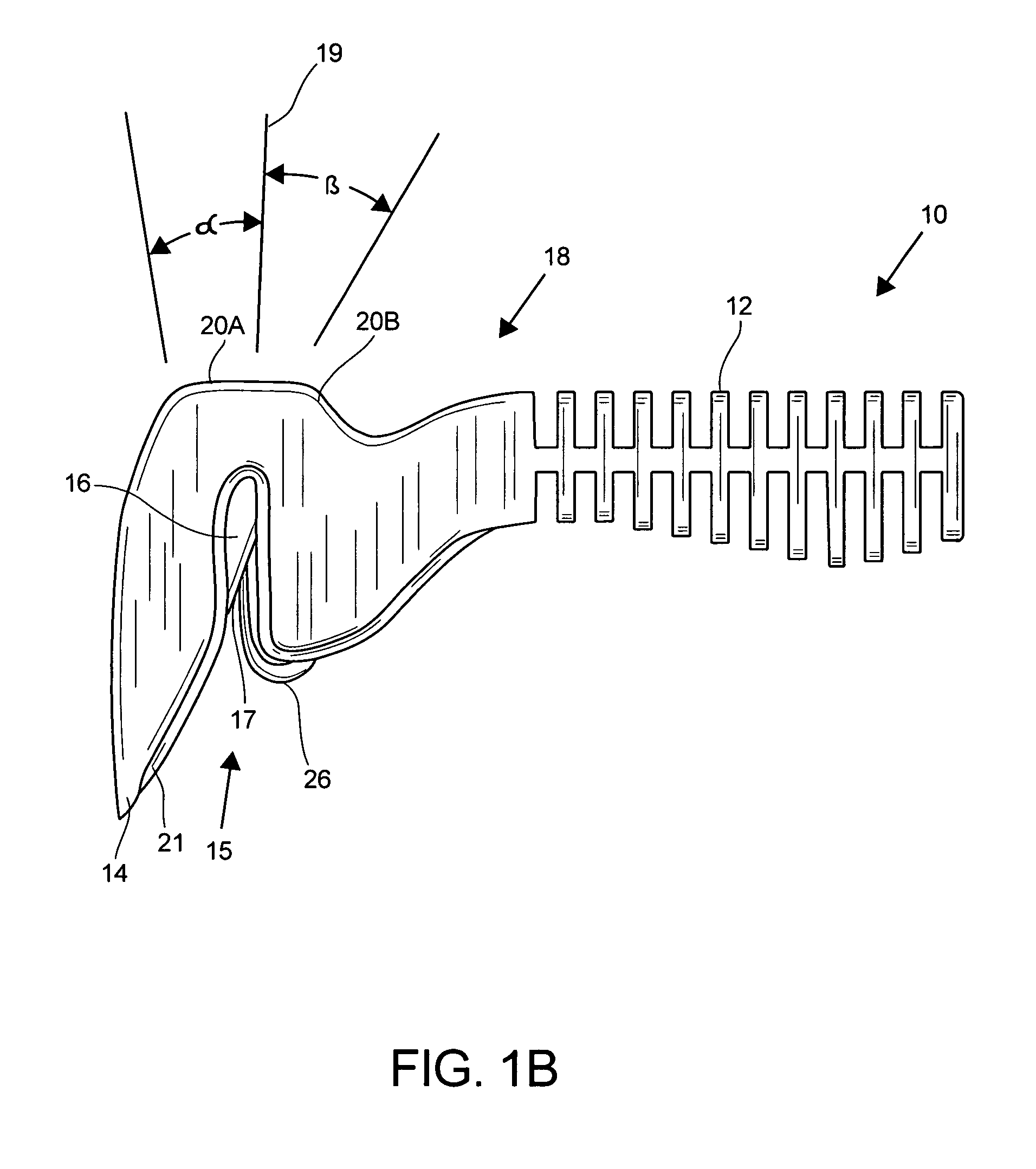
[0035]FIGS. 1A, 1B, and 1C are first, second and third perspective views of a cutter in accordance with the present invention. A cutter 10 includes a handle 12 that is ribbed to provide a gripping surface, to cut down on weight, and to provide for lateral rigidity of the unit.
[0036]The handle 12 is coupled to a body portion 18 that is partitioned into left and right spaced-apart body sections 20A, 20B. The left and right body sections 20A, 20B each include a blade 16A, 16B that has an exposed edge 17A, 17B as shown. The sharpness of the blade edges 17A, 17B are appropriate for readily slicing through a sheet of material to be cut, such as plastic sheeting. In one example, the dual blades 16A, 16B comprise sharpened stainless steel, metal, or metalalloy. The exposed blade edges 17A, 17B are preferably oriented to be aligned with the direction of force that is applied to the cutter 10 when cutting the sheet of material. The dual blades 16A, 16B are spaced apart a distance d1, for exa...
PUM
Property
Measurement
Unit
Distance
aaaaa
aaaaa
Distance
aaaaa
aaaaa
Distance
aaaaa
aaaaa
Abstract
A cutter operative to pierce and cut a sheet of material includes a handle and a body portion coupled to the handle. The body portion includes two puncture fingers having tips for piercing the sheet of material and two blades for cutting two parallel cuts in the sheet of material. in a method of installing a zipper on a sheet of material, left and right portions of a zipper are applied to a sheet of material. A swath portion of the sheet of material is cut having two parallel, spaced-apart cuts between the left and right portions of the zipper. In this manner, zipper installation is established in a manner that avoids formation of flap of material that would otherwise remain between the left and right flanges of the zipper.
Description
RELATED APPLICATION[0001]The present application claims the benefit of U.S. Provisional Application No. 60 / 625,988, filed Nov. 8, 2004, the entire content of which is incorporated herein by reference.BACKGROUND OF THE INVENTION[0002]In the installation of temporary dust partitions, for example of the type disclosed in U.S. Pat. No. 5,924,469, U.S. Ser. No. 10 / 600,939, filed Jun. 20, 2003, U.S. Ser. No. 10 / 600,300, filed Jun. 20, 2003, and U.S. Ser. No. 11 / 125,583, filed May 10, 2005 the contents of each being incorporated herein by reference, a plastic sheet of material, or other type of material sheeting, is installed between a ceiling and a floor of a room to isolate or seal portions of a room from airborne dust or fumes.[0003]In such partition installations, especially in longer-term installations, it has become popular to apply a zippered opening in the plastic sheeting, to allow for rapid entry and exit to and from the partitioned area. Examples of zippers of this type are disc...
Claims
Application Information
Patent Timeline
Application Date:The date an application was filed.
Publication Date:The date a patent or application was officially published.
First Publication Date:The earliest publication date of a patent with the same application number.
Issue Date:Publication date of the patent grant document.
PCT Entry Date:The Entry date of PCT National Phase.
Estimated Expiry Date:The statutory expiry date of a patent right according to the Patent Law, and it is the longest term of protection that the patent right can achieve without the termination of the patent right due to other reasons(Term extension factor has been taken into account ).
Invalid Date:Actual expiry date is based on effective date or publication date of legal transaction data of invalid patent.

