System and method for packet processor status monitoring

a status monitoring and packet processor technology, applied in the field of computer networking, can solve the problems of limiting the achievable data throughput and the packet format which can be handled, and achieve the effect of more robustness

Active Publication Date: 2009-05-26
EXTREME NETWORKS INC
View PDF8 Cites 53 Cited by
  • Summary
  • Abstract
  • Description
  • Claims
  • Application Information

AI Technical Summary

Benefits of technology

[0007]The present invention provides a more robust and more flexible system and method for monitoring the status of an ingress packet processor and an egress packet processor. The present invention allows for off chip monitoring by a host processor and universal location monitoring through a debug port that may provide status data accompanied by a packet header.

Problems solved by technology

However, these architectures are subject to various bottlenecks and constraints which limit the achievable data throughput and the packet formats which can be handled with these architectures.

Method used


Image

  • System and method for packet processor status monitoring
  • System and method for packet processor status monitoring
  • System and method for packet processor status monitoring

Examples


second embodiment

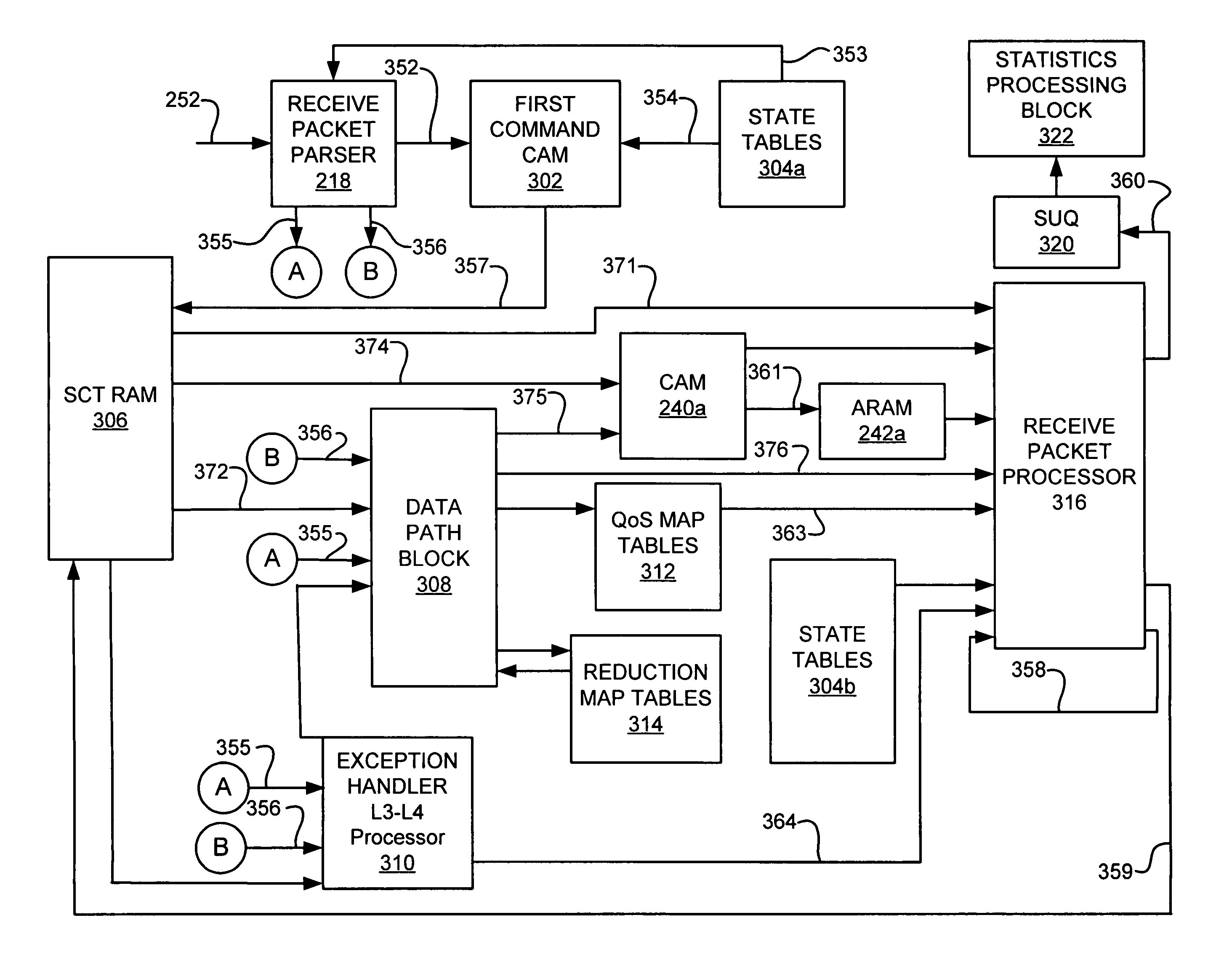
[0054]In one embodiment, the datagram undergoing processing by the packet processor 112 has a plurality of encapsulated layers, and the receive packet parser 218, the first transmit parser 226, and the second transmit parser 230 are configured to parse the datagram by providing context pointers pointing to the start of one or more of the encapsulated layers. In a second embodiment, the datagram undergoing processing by the system includes a first packet forming the payload portion of a second packet, each of the first and second packets having a plurality of encapsulated layers, and each of the receive packet parser 218, the first transmit parser 226, and the second transmit parser 230 are configured to parse the datagram by providing context pointers pointing to the start of one or more of the encapsulated layers of the first packet and one or more of the encapsulated layers of the second packet.

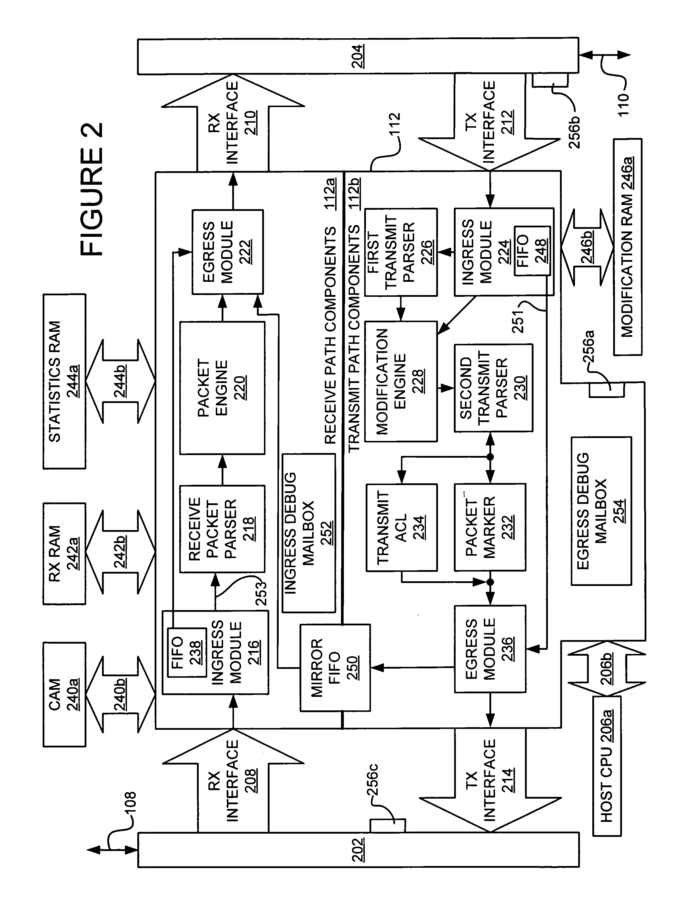
[0055]Receive packet engine 220 executes a number of operations on ingress data packets...

embodiment 400

[0203]FIG. 4 shows a flowchart of an embodiment 400 of the functions associated with receive components 112a of packet addressor 112 of FIG. 1. In block 402, an ingress data packet is provided by the external network receive interface 208. The ingress data packet may include packets such as but not limited to Ethernet, PoS Bridged and PoS Routed services. The ingress data packet is written into a memory element such as receive FIFO 238. The block 402 memory element may be a portion of receive ingress module 216. Receive packet parser 218, which in one embodiment is programmable, processes and decodes the various packet fields. Receive packet parser 218 generates various context pointer fields providing, for example but not limited to, L2, L3 & L4 frames of reference. Receive packet parser 218 also extracts the EtherType or LLC field. The MAC DA may be decoded to provide indicators such as, but not limited to, RADDR, multicast and broadcast indicators. In addition, receive packet par...

embodiment 600

[0246]FIG. 6 illustrates an embodiment 600 of a packet addressor 112 of FIG. 1. In this embodiment, packet addressor 112 is coupled to one or more network-side devices through a multi-port packet bus (PBUS) 602, as described in U.S. patent application Ser. Nos. 10 / 405,960 and 10 / 405,961, filed Apr. 1, 2003, which are both hereby fully incorporated herein by reference. PBUS ingress logic 604 is configured to detect a start of packet (SOP) condition for packets arriving at packet addressor 112 over PBUS 602.

[0247]Upon or after detection of the SOP condition, the packet, or a portion thereof, is stored in a slicer 606. Slicer 606 is configured to slice some or all of a packet into portions and provide the portions in parallel over first data path 608 having a first width to classification engine 610. In one embodiment, the slicer 606 is a FIFO which stores the first 128 bytes of a packet (or the entirety of the packet if less than 128 bytes), and provides the 1024 bits thereof in paral...


PUM


Abstract

Disclosed herein are a system and method for status monitoring, including debug error detection, during data packet processing. In general terms, the system for status monitoring during data packet processing can be implemented as a system including a packet processor and a buffer. The packet processor generates processing data based on one or more control structures while revising packet data. The packet processor generates the processing data while performing one or more lookup cycles. The buffer records the processing data and the status of the one or more control structures. The processing data includes a lookup number and the lookup number identifies the number of cycles performed by the packet processor.

Description

RELATED APPLICATIONS[0001]The following applications are commonly owned by the assignee hereof, are being filed on even date herewith, and are each incorporated by reference herein as though set forth in full:[0002]Howrey Dkt. No.Extreme Dkt. No.Title11 / 860045PACKET PROCESSINGSYSTEMARCHITECTURE ANDMETHOD11 / 924523PACKET PROCESSINGSYSTEMARCHITECTURE ANDMETHOD10 / 724457PACKET DATAMODIFICATIONPROCESSOR10 / 814552METHOD AND SYSTEMFOR INCREMENTALLYUPDATING ACHECKSUM IN ANETWORK DATA PACKET10 / 814556SYSTEM AND METHODFOR EGRESS PACKETMARKING10 / 806426SYSTEM AND METHODFOR ASSEMBLING ADATA PACKET10 / 814727PACKET DATAMODIFICATIONPROCESSOR COMMANDINSTRUCTION SET10 / 814774DATA STRUCTURESFOR SUPPORTINGPACKET DATAMODIFICATIONOPERATIONS60 / 558039RECEIVE-SIDE PACKETPROCESSING SYSTEMFIELD OF THE INVENTION[0003]This invention relates to the field of computer networking, and more specifically, a system and method for status monitoring, including debug error detection, during data packet processing.RELATED ART[...

Claims


Application Information

Patent Timeline
Patent Type & Authority Patents(United States)
IPC IPC(8): G06F15/16G06F12/00
CPCG06F15/16
Inventor PARKER, DAVID K.SWENSON, ERIK R.YOUNG, CHRISTOPHER J.
Owner EXTREME NETWORKS INC
Why Eureka
Try Eureka