Electro-orthodontic device

a technology of electro-orthodontics and orthodontic appliances, applied in the field of electro-orthodontics, can solve the problems of inability to shorten the treatment time by increasing the force, the treatment time is usually longer, so as to reduce the number of wires and connections, the effect of reducing the size of the spa

Active Publication Date: 2014-01-23
ADVANCED ORTHODONTICS & EDUCATION ASSOC LLC
View PDF17 Cites 60 Cited by
  • Summary
  • Abstract
  • Description
  • Claims
  • Application Information

AI Technical Summary

Benefits of technology

[0035]Alternatively, separate electrodes can be provided for each tooth, or a small group of teeth, allowing very specific electric fields to be applied as needed on a tooth-by-tooth or quadrant basis. However, a single electrode is preferred as minimizing the wires and connections and thus much simpler to build, having a smaller footprint, and being more robust. Thus, with 4 cathodes and 4 anodes, every tooth surface can be contacted. If preferred, only one of the lingual or facial surfaces of the teeth and periodontal tissue can be treated, thus requiring only 4 electrodes, instead of 8.
[0071]In use, the bite plate is placed into the patient's mouth, and the patient holds the device by biting down on the bite plate. No other attachment means are needed, and this greatly improve patient acceptance of the device over the prior art bulky headgear or semi-permanent electrode attachment devices. The device is activated and micro-current applied for at least 5-30 minutes daily, preferably 10-20 minutes at least once a day, or 2-4× per day.

Problems solved by technology

Any variations therefrom results in malocclusion.
Although effective, this widely practiced orthodontic treatment takes about twenty-four months on average to achieve success.
Furthermore, treatment time cannot be shortened by increasing the force due to pain and risk of root resorption from the excess force.
The long treatment time, associated pain and the unpleasant aesthetics discourage patients from using such treatment.
Indeed, some studies show that 75 percent of Americans could benefit from orthodontic treatment, yet remain untreated.
However, since the device can be taken off, treatment times usually are longer.
It is also more limited in the classifications of malocclusion that can be addressed since force is not easily applied in all directions.
The early Mao and similar studies provided a basis for both possible efficacy and likely safety for using vibration in humans to assist orthodontic tooth movement, but the animal studies needed to be repeatable in humans, and the devices used by Mao and the others were completely unsuitable for human clinical use, involving clamping a rabbit head in a fixation device, and applied force to the cranium to assess sutural osteogenesis.
Further, Mao used cyclic forces of 5 Newtons (N) and 0.2-1 Hz and such forces are probably too high for human use, both from comfort and root resorption perspectives.
Finally, the device is slim, capable of hands free operation, lacks the bulky head gear of prior art devices, and has optimized force and frequency for orthodontic remodeling.
However, no dedicated device was built by these researchers, who used an experimental set-up, completely inappropriate for human use.
However, being completely intraoral, complex and requiring semi-permanent attachment of electrodes, the device was impractical and never commercialized.
This device is also less than practical, both because it targets one tooth at a time, but also because it placed the electricity generating portion of the device inside the mouth, which has limited room and raises the potential of shorts or leaks, and the resulting unpleasant consequences.
Therefore, this device is impractical or inappropriate for dental remodeling uses.

Method used


Image

  • Electro-orthodontic device
  • Electro-orthodontic device
  • Electro-orthodontic device

Examples


Embodiment Construction

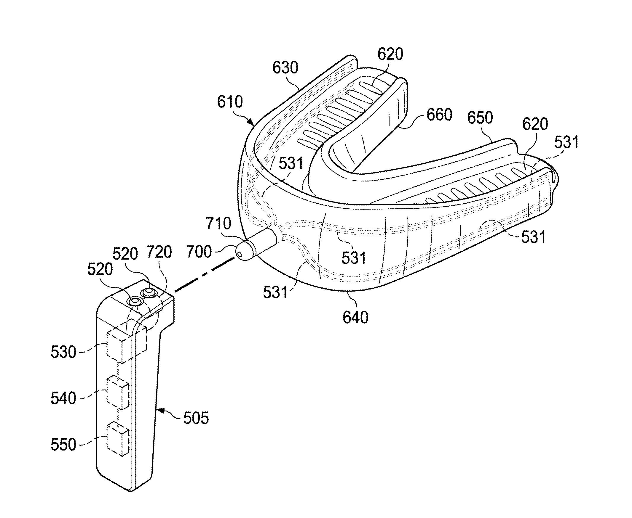
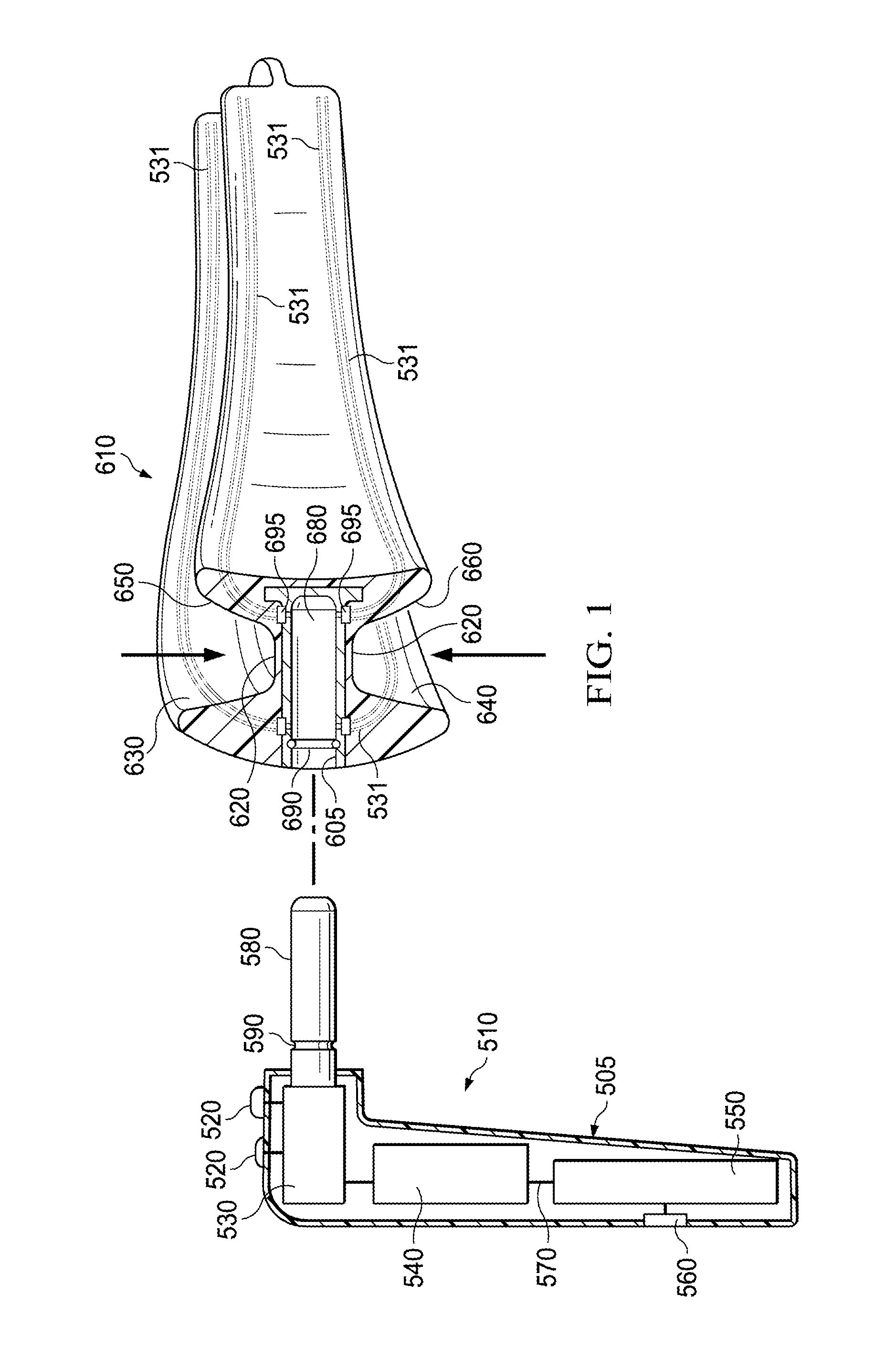
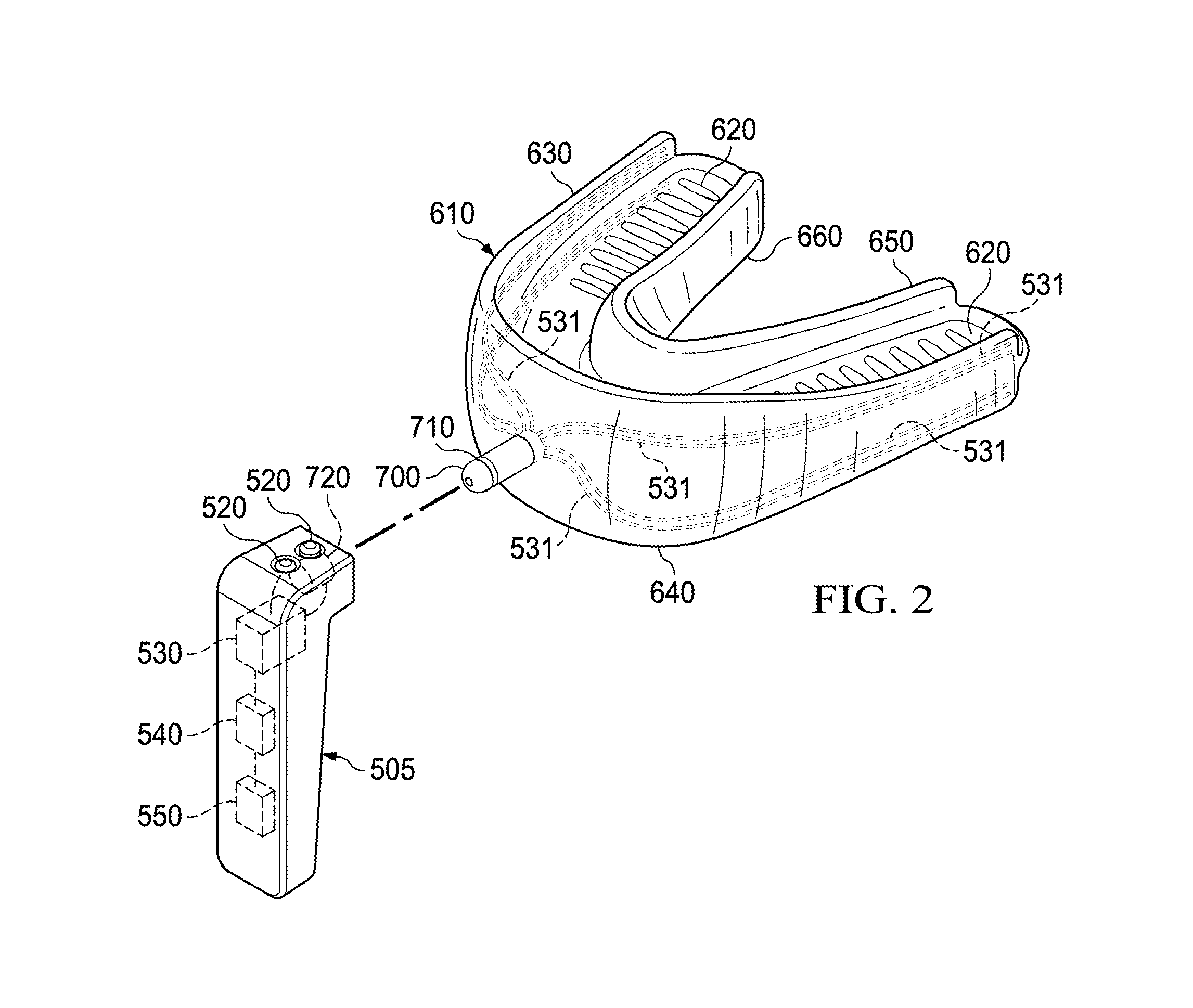
[0084]The disclosure provides a novel electro-orthodontic remodeling device having a special bite plate that contacts lingual and facial teeth surfaces, in addition to occlusal surfaces, and has electrodes thereon for provide current or EM fields to the teeth and / or periodontal tissue.

[0085]The invention can comprise one or more of the following embodiments, in any combination:[0086]An electro-orthodontic remodeling device comprising: an intraoral bite plate having a substantially U-shaped surface for contacting an occlusal surface of teeth; said U-shaped bite plate having an outside edge having upper and lower rims to contact upper and lower facial surfaces of teeth and gums; said upper and lower rims having anodes and cathodes on tooth and gum contacting surfaces thereof; an extraoral waterproof housing containing a power source operably coupled to a processor for controlling said voltage source and providing said anodes and cathodes with either: a current of less than 100 μAmp at...


PUM


Abstract

An electro-orthodontic appliance is provided that helps accelerate orthodontic tooth movement through the application of a controlled electrical current to gum and teeth, thus stimulating osteogenesis.

Description

PRIOR RELATED APPLICATIONS[0001]This application claims priority to 61 / 673,236, filed Jul. 18, 2012 and incorporated by reference in its entirety.FEDERALLY SPONSORED RESEARCH STATEMENT[0002]Not applicable.REFERENCE TO MICROFICHE APPENDIX[0003]Not applicable.FIELD OF THE INVENTION[0004]The invention relates to devices used to speed orthodontic remodeling, in particular an electro-orthodontic device is described that stimulates orthodontic remodeling by micro-pulsed currents or electromagnetic fields.BACKGROUND OF THE INVENTION[0005]A malocclusion is a misalignment of teeth or incorrect relation between the teeth of the two dental arches. The term was coined by Edward Angle, the “father of modern orthodontics,” as a derivative of occlusion, which refers to the way opposing teeth meet. Angle based his classifications of malocclusions on the relative position of the maxillary first molar. According to Angle, the mesiobuccal cusp of the upper first molar should align with the buccal groo...

Claims


Application Information

Patent Timeline
Patent Type & Authority Applications(United States)
IPC IPC(8): A61C7/00
CPCA61C7/006A61C7/008A61C7/08A61C7/36B33Y80/00
Inventor LOWE, MICHAEL K.SWOL, LAWRENCE W.
Owner ADVANCED ORTHODONTICS & EDUCATION ASSOC LLC
Why Eureka
Try Eureka