Clip-on protective kneepad

a protective knee and clip-on technology, applied in the field of protective knee pads, can solve the problems of affecting the comfort of wearers, and affecting the comfort of wearers, and achieve the effect of more comfort and protection

Active Publication Date: 2011-05-31
WILLIAMS JR JAMES D
View PDF10 Cites 5 Cited by
  • Summary
  • Abstract
  • Description
  • Claims
  • Application Information

AI Technical Summary

Benefits of technology

[0011]The protective kneepads include connectors integrated into the side edges of the pads and directly connect the kneepads to the pants of the wearer. No straps are required to extend from the kneepad to the connectors. The connectors are configured to gather and connect to the material of the pant legs with the gathered material extending at the side edges of the kneepad. This tends to minimize any looseness of the connection to the pant legs, and minimize any “droop” of the kneepad from the pant legs.
[0024]If desired, the kneepads may be formed in a concave shape so as to extend generally about the knees so that the kneepads tend to find their own positions about the knees when the wearer moves to the kneeling position. Also, the kneepads may have a hard exterior and a soft liner for more comfort and protection.

Problems solved by technology

If the straps are drawn tightly about the limb, they tend to hold the kneepad in place, but the tighter the straps the more constriction and discomfort there is about the limbs.
This generates an undesirable constriction in the blood flow and discomfort to the wearer.
However, when the wearer stands and the knee is straightened, the pants of the wearer become somewhat bunched above the kneepad, and there is some tendency of the kneepads to slip downwardly with the pants, to a position lower than the desired position.
When the wearer returns to the kneeling position, the constriction of the straps tends to impede the lifting movement of the kneepads that is necessary to move the kneepads back up to the desired position at the knee.
Similar problems are experienced with elbow pads and other pads that have straps that encircle the limbs of the body.
The placement of the fasteners at the distal ends of the straps may form the desired loose connection of the straps to the pants legs but tends to allow the pads to sag downwardly and away from the pants legs so that the kneepads are not accurately held in the position for registering with the knees when the wearer kneels.

Method used


Image

  • Clip-on protective kneepad
  • Clip-on protective kneepad
  • Clip-on protective kneepad

Examples


Embodiment Construction

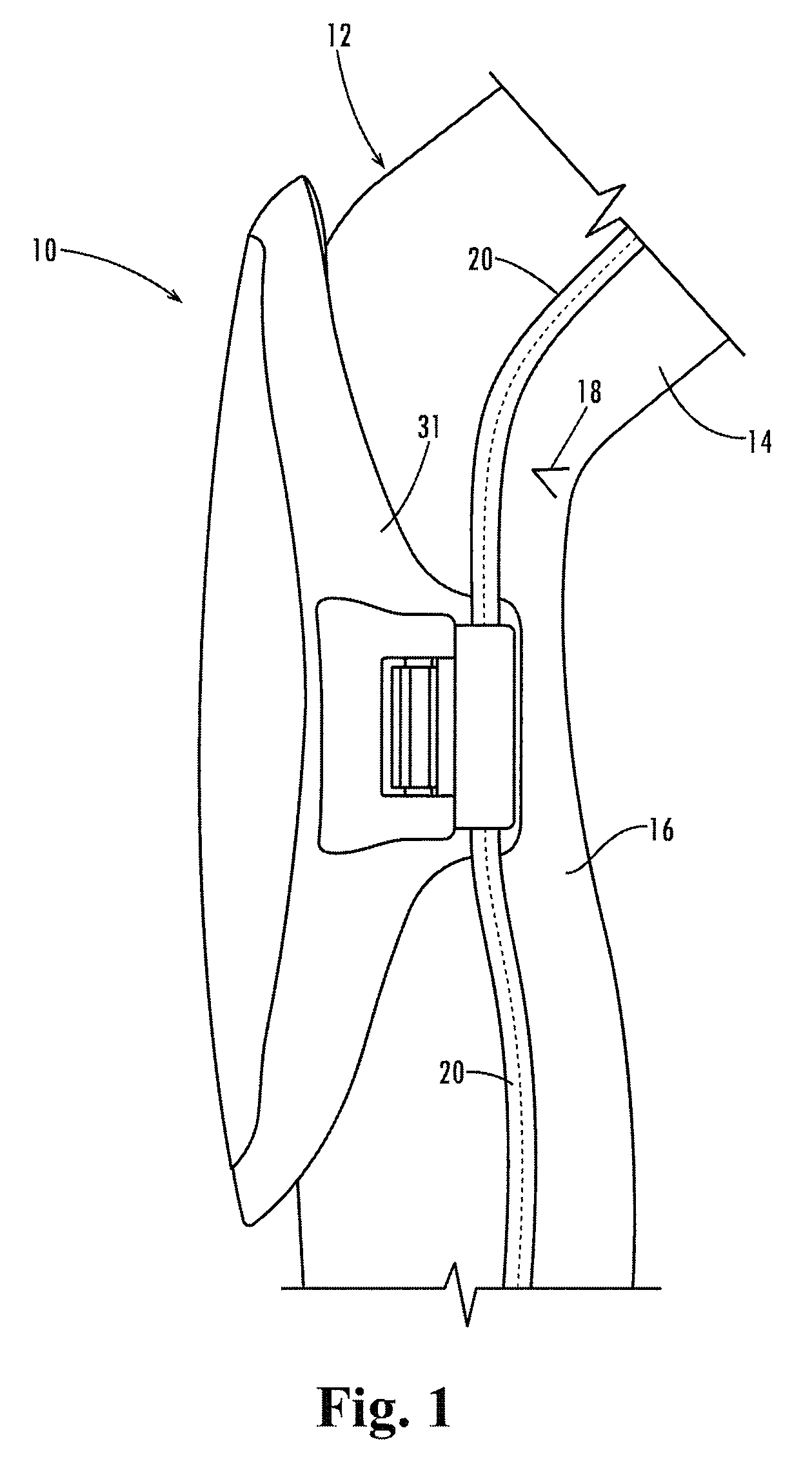
[0033]Referring now in more detail to the drawings, in which like numerals indicate like parts throughout the several views, FIG. 1 illustrates a kneepad 10 for connection to the pant leg 12 of a wearer of the pant leg. The pant leg and the wearer have a thigh 14, a calf 16, and a knee that is between the thigh and calf, with position of articulation of the knee indicated at the back of the knee 18 shown behind the kneepad 10. The pant leg may include vertical seams, such as seam 20, and the kneepad 10 typically is connected to the seams of the pant leg.

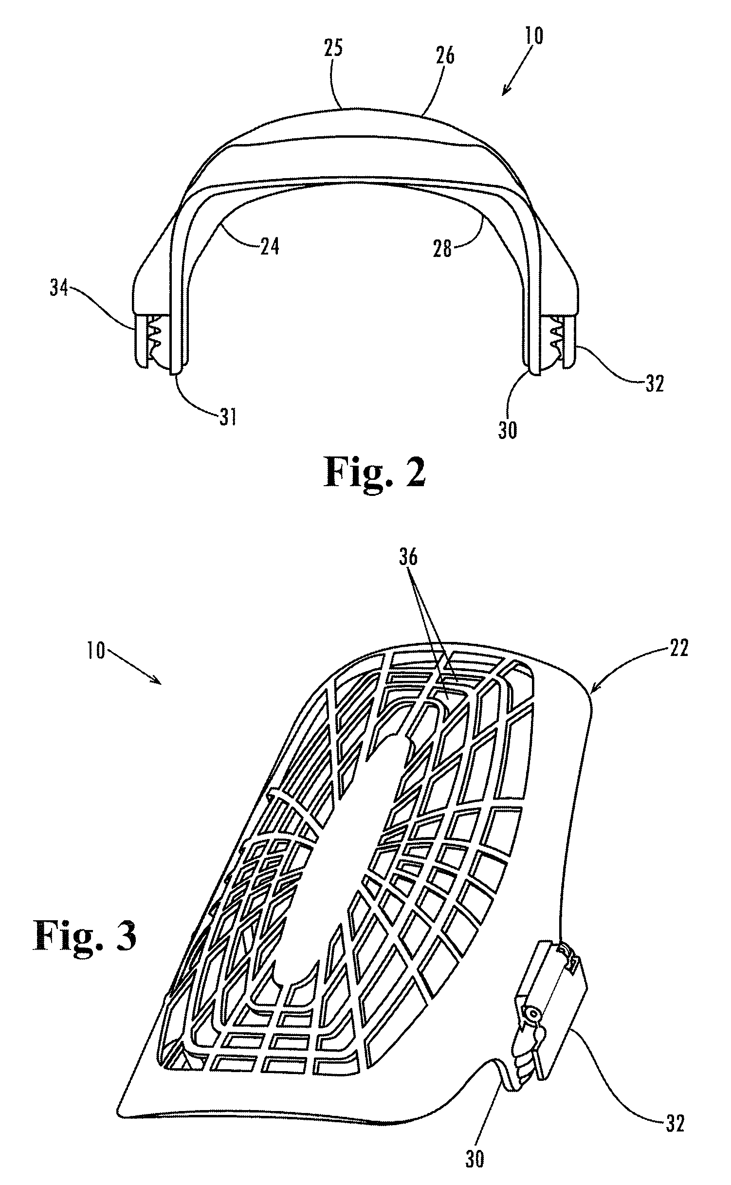
[0034]As shown in FIG. 3, the kneepad 10 includes an protective hard shell 22. As shown in FIG. 2 the kneepad has inner and outer layers of soft material 24 and 25 applied to the inner protective shell. The protective shell may be made of a hard yet flexible plastic such as a thermoplastic urethane, polyurethane, polyvinylchloride, polypropylene or other suitable similar compound and the softer material applied to the protective shel...


PUM


Abstract

A kneepad includes connectors (32 and 34) at its lower side edges (30 and 31) below the position of articulation of the joint. The connectors are biased toward a plurality of ribs (40) integrally formed in the external side surface of the outer hard shell (22) for trapping the side seams of the pant leg against the ribs and holding the kneepad firmly in place.

Description

CROSS REFERENCE TO RELATED FILE[0001]Applicant claims the benefit of co-pending provisional patent application 60 / 846,660 filed Sep. 22, 2006.FIELD OF THE INVENTION[0002]This invention concerns protective pads worn on the body, such as kneepads, that are strapless, non-constricting and that attach to the pants legs of a wearer.BACKGROUND OF THE INVENTION[0003]Protective kneepads have been available for people to wear on their bodies, such as kneepads, elbow pads, shin pads, thigh pads, forearm pads, etc.[0004]The pads protect the limbs of the body from injury and provide comfort to the wearer.[0005]Some pads have straps that are connected to the edges of the pads and extend about the limb so as to have enough frictional contact to cling to the leg, arm, etc. Typically, the pads require upper and lower straps for connection to the limbs. For example, kneepads usually have upper straps to be wrapped from the upper portions of the kneepads around the legs above the knees and lower stra...

Claims


Application Information

Patent Timeline
Patent Type & Authority Patents(United States)
IPC IPC(8): A41D13/00
CPCA41D13/065A41D13/0556A41D13/0158
Inventor WILLIAMS, JR., JAMES D.
Owner WILLIAMS JR JAMES D
Why Eureka
Try Eureka