Apparatus and Method for Sensing a Time Varying Ionic Current in an Electrolytic System

a technology of electrolysis and apparatus, applied in the field of electrolysis sensing systems, can solve the problems of high sensitivity of electrolysis, and high cost, and achieve the effects of reducing capacitance, reducing system internal noise, or current noise, and increasing sensitivity

Active Publication Date: 2009-08-06
ELECTRONICS BIOSCI
View PDF7 Cites 9 Cited by
  • Summary
  • Abstract
  • Description
  • Claims
  • Application Information

AI Technical Summary

Benefits of technology

[0018]In contrast to the prior art systems discussed above, the system built in accordance with the present invention has a total capacitance at an amplifier input, including the amplifier itself, of 2-10 pF. This dramatic reduction in the capacitance provides a reduction in the system's internal noise, or current noise, thereby providing a significant increase in sensitivity. This improvement can be utilized whether a system orifice is open, as when a resistive pulse technique is utilized to count and size particles, or whether a membrane and ion channel are present across the orifice. Further, the reduction in internal noise enables measurements to be conducted at bandwidths well beyond the range of prior art systems. Because of its improved sensitivity, the apparatus allows use of a reduced ionic current. This enables implementation with the use of a lower bias voltage or the use of lower concentration electrolytes. Advantageously, the system of the present invention is no more difficult to use, and no more expensive than prior art technology.
[0019]The present invention provides higher measurement sensitivity and bandwidth by combining three specific approaches to minimize the capacitance connected to the first stage amplifier input. First, the apparatus includes an orifice having a lateral dimension that is less than 10 μm, and less than 50 nm in the case that no membrane seals the orifice. Secondly, to take advantage of the very small orifice capacitance, the capacitance connecting the first and second fluid volumes that appears across the substrate containing the one or more orifices is less than 1 pF and preferably less than 0.25 pF. This is achieved by minimizing the area of the substrate that is exposed to the fluid and making the substrate sufficiently thick. Thirdly, the measurement electrodes and first stage amplifier are integrated Within 5 cm of the nanoscale orifice, and novel circuit designs and packaging provide very high sensitivity for very high input impedance within a small overall volume.
[0020]With this preferred arrangement, the ionic current flowing through a small fluid orifice or ion channel is measured with a sensitivity and bandwidth that significantly exceeds prior methods. The fundamental parameter of interest, is the time variation of the ionic current. However, other physical variables such as leakage current of the membrane or another steady state, or quasi steady state property could, in some cases, be a parameter of interest. In the preferred embodiment of an ion channel spanning a membrane, the ion channels can be of their natural form or be engineered or otherwise modified as desired for specific properties. A particular application of the invention is to measure discrete conductivity states in ion channels. These states change stochastically in the presence of analytes in a manner that allows separate determination of concentration and species. Another application of the invention is to measure channel current when conductivity is simply determined by a blocking effect produced by the presence of an analyte in the orifice, as in the conventional Coulter counter.

Problems solved by technology

Indeed, many of the biologically and medically important ion channels have unmeasurable single channel currents, and their conductance must be estimated from macroscopic measurements of many ion channels.
In addition to a need to be able to record smaller current changes, it is generally believed that the speed of many ion channel transitions is faster than the response time of existing recording systems and thus these channels have gone unmeasured.
The former method permits macroscopic access from both sides of the membrane, but is very fragile.
In addition, the very small fluid volume in the region between the membrane and solid surface prevents the use of traditional direct current (DC) methods to measure channel current because of the build up of ionic concentration gradients across the membrane.
Regarding measurement sensitivity and bandwidth, conventional ion channel recordings are limited by the current noise of the first stage amplifier, and the effective current noise produced by the voltage noise of the first stage amplifier acting on the total capacitance at the amplifier input.
Although it is possible to immerse a pipette tip by only a very small distance, it is cumbersome to set up, and difficult to implement for any length of time because of the fluid level change due to evaporation.
However, this represents a trade-off in the first stage amplifier design for the known input impedance, and the two conventional types of measurement apparatus ultimately reach limitations inherent to their mechanical designs.
For the patch pipette, the limitation is the pipette itself.
For the Teflon cup, the limitation is the area of the membrane.

Method used


Image

  • Apparatus and Method for Sensing a Time Varying Ionic Current in an Electrolytic System
  • Apparatus and Method for Sensing a Time Varying Ionic Current in an Electrolytic System
  • Apparatus and Method for Sensing a Time Varying Ionic Current in an Electrolytic System

Examples


first embodiment

[0044]Another possible configuration is for membrane 30 to be located on the inside of substrate 14, i.e. within the sensing volume 8, rather than electrolyte bath 4. This embodiment relates to an apparatus 2′ shown in FIG. 5, which is a structure especially applicable to producing an array of sensing elements in a solid material such as a silicon wafer. It uses the bulk of the solid material (e.g. Si) to provide a thick wall barrier 12′ with a base 40, such as PDMS, on the bottom of barrier 12′ to create a small fill line 42 to allow access to a sensing volume 8′. An ion channel (not shown in FIG. 5 but corresponding to ion channel 32 of the first embodiment) is inserted into a membrane 30′ from a bath side 4′ via a nanopore or orifice 22′ in a barrier 12′. If desired, an electrophoretic or conducting ring 48 is made on barrier 12′ around the orifice 22′ region, and is raised to a desired potential in order to provide an electrostatic force to aid in channel addressing. One benefit...

embodiment 2

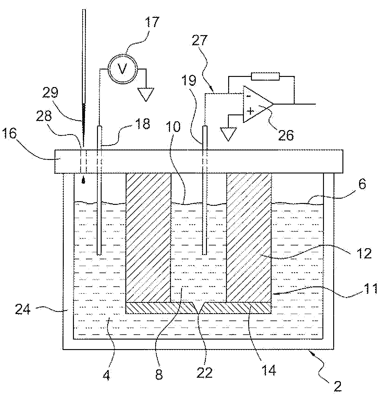
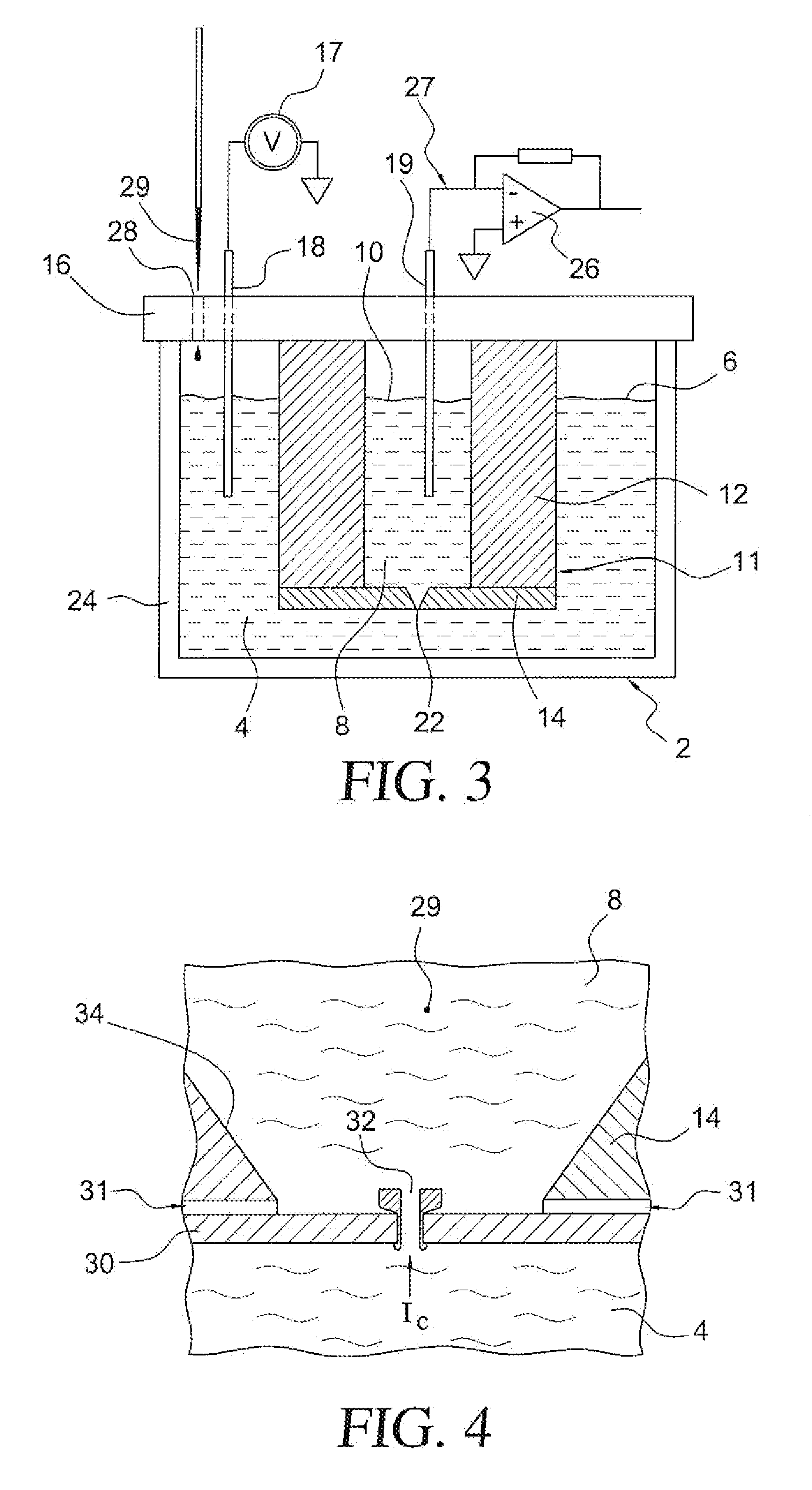
[0049]A method of utilizing a continuous sampling embodiment 2″ of the present invention will now be discussed with reference to FIG. 9. System 2″ includes an electrolyte bath or fluid delivery element 104 and an electrolyte bath 108 provided with an electrolyte 110. Fluid delivery element 104 is separated from electrolyte bath 108 by a structure 111 comprised of a thick wall barrier 112 and a substrate 114. Additionally, a mounting substrate 116 extends across the top of electrolyte bath 108. Measurement electrodes 118 and 119 extend into fluid delivery element 104 and electrolyte bath 108, respectively. Substrate 114 contains an orifice 122. Recording electronics 126 are connected to electrode 119 by a conductor wire 127. A voltage source 117 is connected to bath electrode 118 and referenced to the system electrical ground. Delivery element 104 is attached to substrate 114 in a fluid-tight manner and contains a fluid-filled channel 154, which passes over orifice 122 for the purpos...


PUM

PropertyMeasurementUnit
total capacitanceaaaaaaaaaa

Abstract

An apparatus and method for sensing time varying ionic current in an electrolytic system having a first fluid chamber and a second fluid chamber separated by a barrier structure is provided, wherein the barrier structure includes thick walls and a substrate having an orifice therein, with the first and second fluid chambers being in communication via the orifice. A potential is applied between electrodes in respective first and second fluid chambers, thus driving an electrical current between them and through the orifice. Total capacitance of the system is less than 10 pF. Analytes are added to one of the first and second fluid chambers and time varying ionic current that passes across the orifice is measured. An amplifier proximal to the barrier structure and electrodes amplifies the ionic current signal.

Description

CROSS-REFERENCE TO RELATED APPLICATION[0001]The present application represents a National Stage application of PCT / US2007 / 011257 filed May 10, 2007 entitled “Apparatus and Method for Sensing a Time Varying Ionic Current in an Electrolytic System”, and claims the benefit of U.S. Provisional Patent Application Ser. No. 60 / 813,712 filed Jun. 15, 2006 entitled “System for Improved Ion Channel Recordings and Related Measurement of Objects and Analytes in Solution.”BACKGROUND OF THE INVENTION[0002]1. Field of the Invention[0003]The present invention pertains to the art of electrolytic sensing systems, and more specifically, to an apparatus and method for sensing a time varying ionic current in an electrolytic environment having improved sensitivity and bandwidth.[0004]2. Discussion of the Prior Art[0005]The measurement of the electrical conductivity of small fluid regions is of importance in many applications. For example, small particles, such as viruses, suspended in a fluid can be coun...

Claims


Application Information

Patent Timeline
Patent Type & Authority Applications(United States)
IPC IPC(8): C12Q1/02G01N27/02
CPCG01N33/48728G01N33/48721
Inventor HIBBS, ANDREW D.POQUETTE, MELISSA ANN
Owner ELECTRONICS BIOSCI
Why Eureka
Try Eureka