Image reconstruction for touch determination

a touch sensor and image reconstruction technology, applied in the field of touch sensing systems and data processing techniques, can solve the problems of significant processing time, difficulty in properly detecting the touch on the touch surface at all, and the degree of interaction between the touching object and the touch surface may vary both, so as to improve the stability and robustness of tracking, avoid or improve the effect of slow variation in the structure of the touch sensor apparatus

Inactive Publication Date: 2014-11-18
FLATFROG LAB
View PDF26 Cites 34 Cited by
  • Summary
  • Abstract
  • Description
  • Claims
  • Application Information

AI Technical Summary

Benefits of technology

[0014]In the method of the first aspect, the differential interaction pattern is generated to represent a change in interaction on the surface portion since the preceding iteration in which the reference values were obtained for the detection lines. By proper selection of the preceding iteration in relation to the current iteration, it is possible to ensure that the maximum change in interaction on the surface portion matches the available bit resolution in the reconstruction processing so as to allow detection of touches with weak interaction with the propagating light. It is thus realized that the use of change values in the reconstruction processing may lower the demand on bit resolution in the reconstruction processing compared to the use of current signal values. Furthermore, a reduction in required bit resolution may lead to a reduction in processing time.
[0029]In one embodiment of the second tracking embodiment, the step of updating the tracking pattern comprises updating the current accumulated touch interaction pattern as a function of touches identified on the surface portion in the current iteration. The updating enables compensation for the influence of contaminations downstream of the reconstruction processing and may provide a simple way of operating on two-dimensional distributions. For example, the step of updating the tracking pattern may comprise estimating an influence of added contaminations to the surface portion and removing the estimated influence from the current accumulated touch interaction pattern. Thereby, the accumulated touch interaction pattern is compensated for the influence of contaminations across the iterations of the method. For example, the accumulated touch interaction pattern may be updated in analogy with the updating of the background pattern as described in aforesaid WO2011 / 049512.

Problems solved by technology

The influence of interferences may vary not only over time but also across the touch surface, making it difficult to properly detect the touches on the touch surface at all times. Furthermore, the degree of interaction between a touching object and the touch surface may vary both over time and between different objects.
However, this is demanding in terms of processing, and may lead to significant processing times. It is also conceivable that the available bit resolution for the reconstruction processing may be limited by hardware constraints.
One challenge, however, is to achieve a sufficiently adequate compensation on the input side.
If attenuation from contaminations remains in the reconstructed image, touch determination may be more or less hampered.
After some time of use, significant contaminations (fingerprints, smear, etc) may have been deposited on the surface portion, resulting in large interaction values in both the tracking pattern and the background pattern.
It is realized that small errors in either of the large numbers may result in significant errors in the calculated difference, which may be a small number.
Specifically, the propagating light may be attenuated by frustration of total internal reflection of light in the touch surface.

Method used


Image

  • Image reconstruction for touch determination
  • Image reconstruction for touch determination
  • Image reconstruction for touch determination

Examples


first embodiment

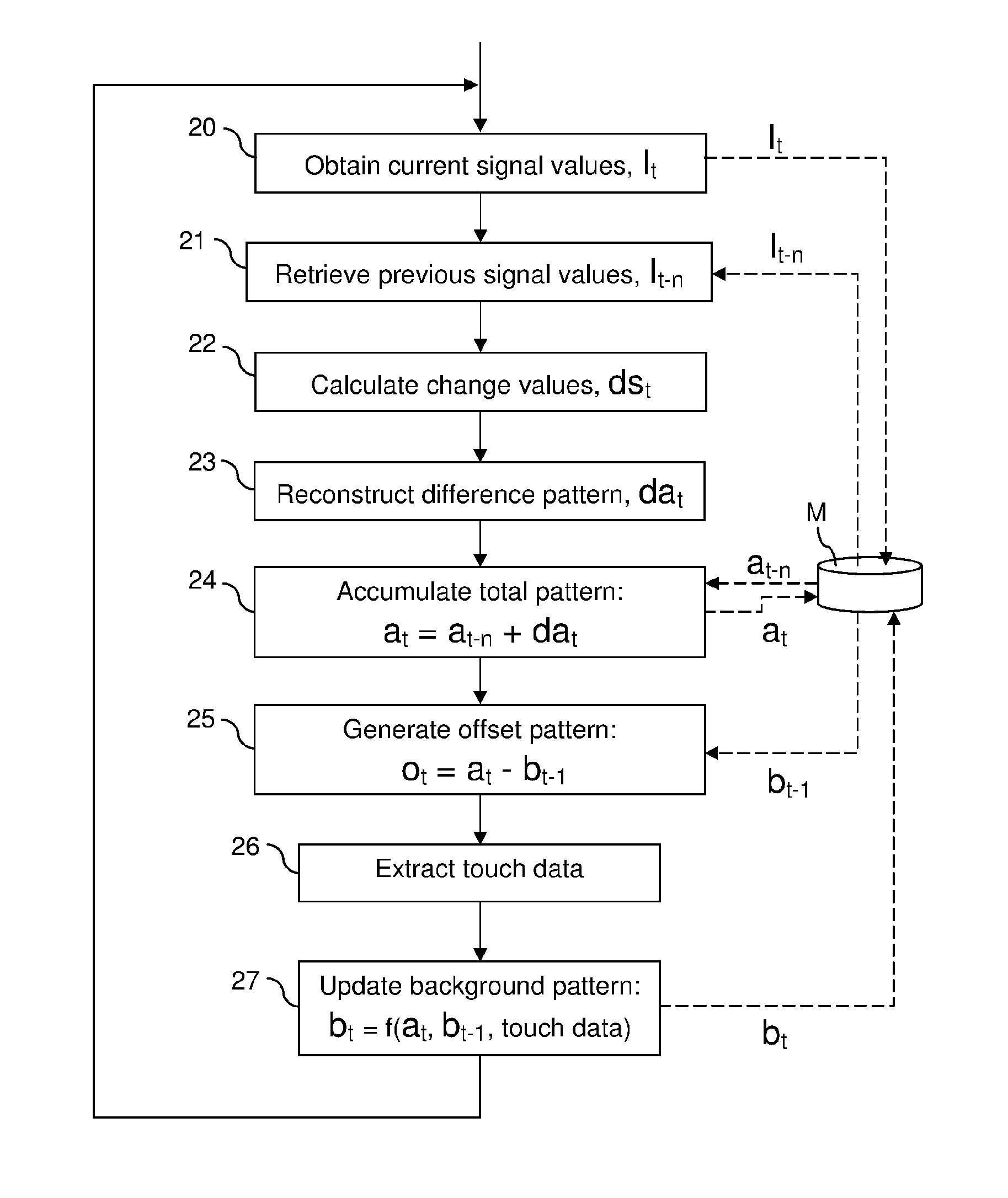
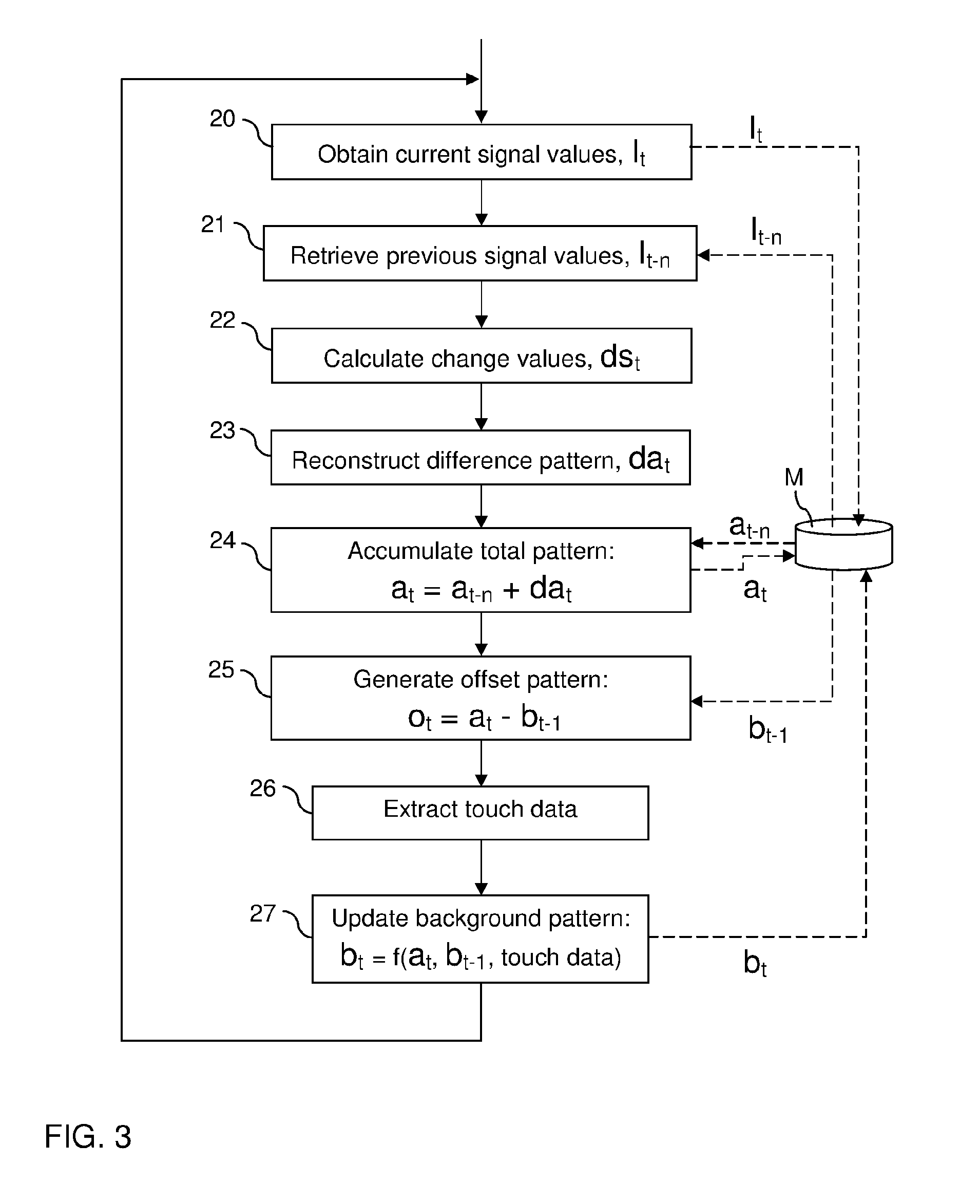
[0075]FIG. 3 shows a method for reconstruction and touch data extraction in a touch-sensitive apparatus, such as the above-described FTIR system. The method involves a sequence of steps 20-27 that are repeatedly executed, typically by the signal processor 10 (FIGS. 1-2). In the context of this description, each sequence of steps 20-27 is denoted an iteration or a sensing instance.

[0076]Each iteration starts by a data collection step 20, in which measurement values are sampled from the light sensors 3 in the FTIR system, typically by sampling a value from each of the aforesaid projection signals. The data collection step 20 results in one projection value for each detection line. It may be noted that the data may, but need not, be collected for all available detection lines in the FTIR system. The data collection step 20 may also include pre-processing of the measurement values, e.g. filtering for noise reduction. For the purpose of the following discussion, the current projection va...

second embodiment

[0100]The second embodiment is based on the insight that it may be advantageous to avoid generating the offset pattern by subtracting a background pattern from the total attenuation pattern (step 25 in FIG. 3). As contaminations are accumulated on the touch surface, the total attenuation pattern at as well as the background pattern bt-1 may contain large attenuation values, at least locally. It is thus possible that significant inaccuracies are introduced in the offset pattern ot even by small errors if large attenuation values are subtracted from each other. Furthermore, detection of small differences between large attenuation values may necessitate undesirably high bit resolution in both the total attenuation pattern at and the background pattern bt-1.

[0101]In the second embodiment, the tracking pattern is formed by a background-compensated version of the offset pattern. As will be shown below, this may obviate the need to calculate or track the total attenuation pattern, as well ...


PUM


Abstract

Touch sensitivity is enabled using a touch system that comprises a panel configured to conduct signals, e.g. by TIR, from a plurality of incoupling points to a plurality of outcoupling points, thereby defining detection lines across a touch surface between pairs of incoupling and outcoupling points. A signal processor operates in a repeating sequence of iterations to: calculate change values for the detection lines representative of signal changes between the current and a previous iteration, and operate a reconstruction algorithm on the change values to determine a differential interaction pattern across the touch surface. The signal processor also operates to update a tracking pattern as a function of the differential interaction pattern, and generate a current offset pattern based on the tracking pattern. The offset pattern is generated to represent current touch interaction on the touch surface and is supplied for identification of touches on the surface portion.

Description

CROSS-REFERENCE TO RELATED APPLICATIONS[0001]This application is the national phase under 35 U.S.C. §371 of PCT International Application No. PCT / SE2012 / 051006 which has an International filing date of Sep. 24, 2012, which claims priority to U.S. provisional patent application number 61 / 539,608 filed Sep. 27, 2011, and to Swedish patent application number SE 1150879-3 filed Sep. 27, 2011.TECHNICAL FIELD[0002]The present invention generally relates to touch sensing systems and data processing techniques in relation to such systems, and in particular to the use of image reconstruction for touch determination in such systems.BACKGROUND ART[0003]Touch sensing systems (“touch systems”) are in widespread use in a variety of applications. Typically, the touch systems are actuated by a touch object such as a finger or stylus, either in direct contact, or through proximity (i.e. without contact), with a touch surface. Touch systems are for example used as touch pads of laptop computers, in c...

Claims


Application Information

Patent Timeline
Patent Type & Authority Patents(United States)
IPC IPC(8): G06F3/042G06F3/041
CPCG06F3/041G06F3/0421G06F2203/04109G06F3/04186
Inventor CHRISTIANSSON, TOMASOHLSSON, NICKLAS
Owner FLATFROG LAB
Why Eureka
Try Eureka