

Ultracompact image pickup lens
a pickup lens, ultra-compact technology, applied in the field of image pickup lenses, can solve the problems of insufficient, insufficient, and insufficient resolving power,
- Summary
- Abstract
- Description
- Claims
- Application Information
AI Technical Summary
Benefits of technology
Problems solved by technology
Method used
Image

Examples
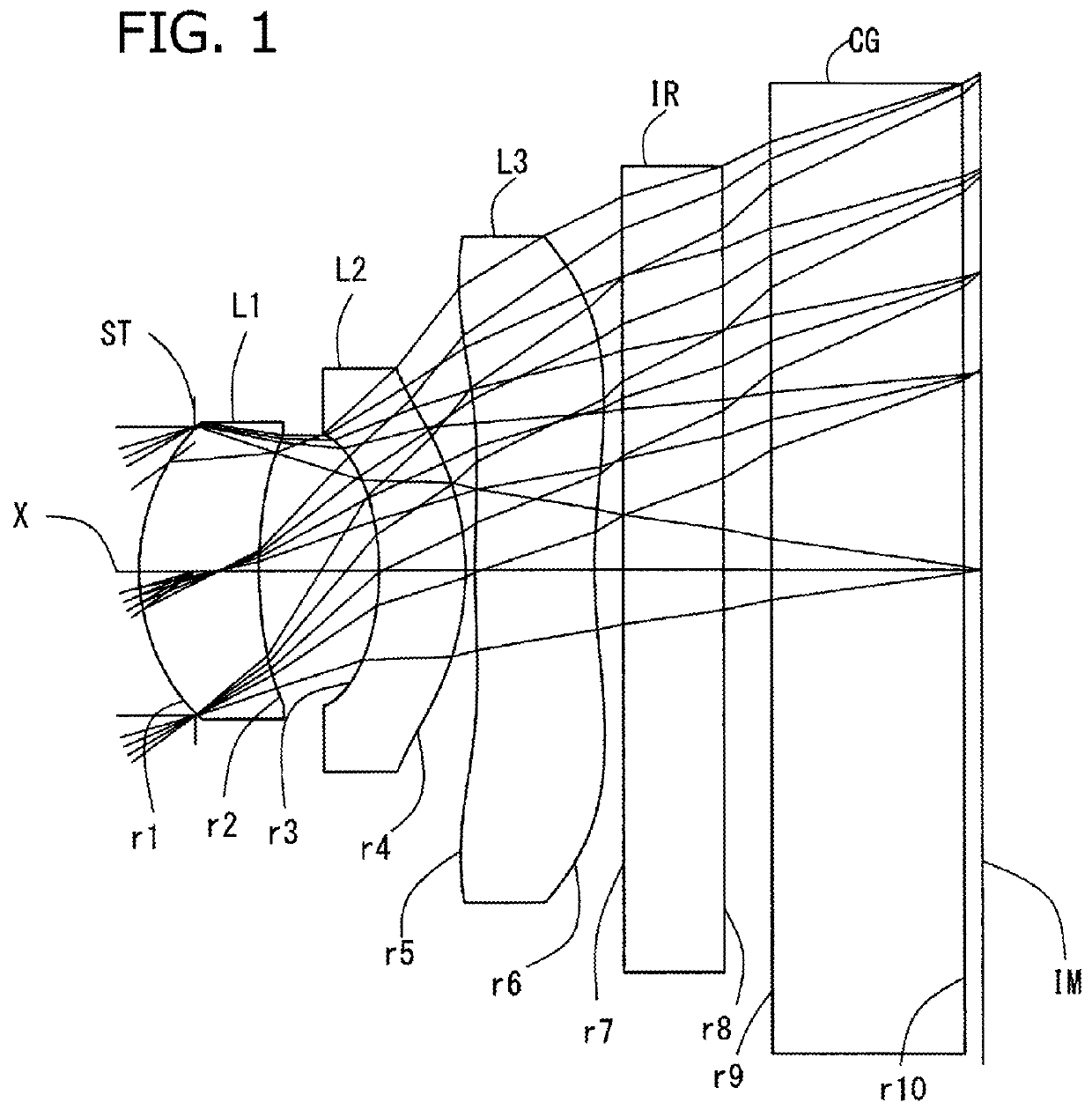
embodiment 1
[0069]Basic lens data will be shown in Table 1 below.
[0070]
TABLE 1Embodiment 1Unit mmf = 1.431Fno = 2.43ω(°) = 35.74IH = 1.028Surface DataCurvatureSurfaceRefractiveAbbe NumberSurface No.Radius rDistance dIndex Ndvd(Object Surface)InfinityInfinity 1 (Stop)Infinity−0.1175 2*0.4400.2501.543855.57 3*1.0020.250 4*−0.5350.1801.543855.57 5*−0.5720.020 6*2.2330.2501.543855.57 7*1.2570.060 8Infinity0.2101.516864.20 9Infinity0.10010Infinity0.4001.516864.2011Infinity0.037Image PlaneInfinityAspherical Surface Data2nd Surface3rd Surface4th Surface5th Surface6th Surface7th Surfacek−1.082E+002.009E+002.564E+00−1.204E+003.045E+00−3.849E+00A41.540E+001.331E+003.955E+00−7.731E−01−3.304E+00−2.202E+00A61.846E+01−1.325E+01−1.783E+02−5.933E−011.175E+015.552E+00A8−1.391E+023.885E+024.741E+03−6.216E+01−2.103E+01−1.297E+01A101.077E+03−2.456E+03−6.095E+041.307E+032.777E+011.872E+01A120.000E+000.000E+003.195E+05−4.900E+03−3.234E+01−2.197E+01A140.000E+000.000E+000.000E+003.100E+012.084E+011.776E+01A160.000E+00...
embodiment 2
[0074]Basic lens data will be shown in Table 2 below.
[0075]
TABLE 2Embodiment 2Unit mmf = 1.435Fno = 2.41ω(°) = 35.68IH = 1.028Surface DataCurvatureSurfaceRefractiveAbbe NumberSurface No.Radius rDistance dIndex Ndvd(Object Surface)InfinityInfinity 1 (Stop)Infinity−0.1175 2*0.4400.2501.543855.57 3*1.0020.250 4*−0.5350.1801.543855.57 5*−0.5720.020 6*2.1370.2501.543855.57 7*1.2020.060 8Infinity0.2101.516864.20 9Infinity0.10010Infinity0.4001.516864.2011Infinity0.038Image PlaneInfinityAspherical Surface Data2nd Surface3rd Surface4th Surface5th Surface6th Surface7th Surfacek−1.082E+002.009E+002.564E+00−1.204E+003.211E+002.336E−02A41.540E+001.331E+003.955E+00−7.731E−01−3.294E+00−2.420E+00A61.846E+01−1.325E+01−1.783E+02−5.933E−011.085E+014.969E+00A8−1.391E+023.885E+024.741E+03−6.216E+01−1.761E+01−1.177E+01A101.077E+03−2.456E+03−6.095E+041.307E+032.563E+012.157E+01A120.000E+000.000E+003.195E+05−4.900E+03−4.094E+01−3.313E+01A140.000E+000.000E+000.000E+003.100E+013.260E+012.739E+01A160.000E+000...
embodiment 3
[0079]Basic lens data will be shown in Table 3 below.
[0080]
TABLE 3Embodiment 3Unit mmf = 1.430Fno = 2.43ω(°) = 35.69IH = 1.028Surface DataCurvatureSurfaceRefractiveAbbe NumberSurface NoRadius rDistance dIndex Ndvd(Object Surface)InfinityInfinity 1 (Stop)Infinity−0.1175 2*0.4410.2481.543855.57 3*1.0010.249 4*−0.5410.1871.543855.57 5*−0.5440.031 6*2.5380.2351.543855.57 7*1.1720.060 8Infinity0.211.516864.20 9Infinity0.10010Infinity0.4001.516864.2011Infinity0.042Image PlaneInfinityAspherical Surface Data2nd Surface3rd Surface4th Surface5th Surface6th Surface7th Surfacek−1.143E+002.544E+002.614E+00−1.189E+004.895E+00−4.792E+00A41.465E+001.463E+004.088E+00−7.883E−01−3.304E+00−2.208E+00A62.039E+01−1.617E+01−1.846E+02−1.360E+001.175E+015.530E+00A8−1.361E+023.960E+024.731E+03−6.435E+01−2.087E+01−1.260E+01A109.620E+02−2.401E+03−6.023E+041.375E+032.772E+011.897E+01A120.000E+000.000E+003.195E+05−4.955E+03−3.243E+01−2.370E+01A140.000E+000.000E+000.000E+002.709E+012.016E+011.872E+01A160.000E+000....
PUM
 Abstract
Description
Claims
Application Information