Pickup lens

a technology of pick-up and lens, applied in the field of pick-up lenses, can solve the problems of inability to use the lens as a compact lens, inconvenient machine-making, and long back focus, and achieve the effects of good quality image, easy machine-making, and short optical length l

Active Publication Date: 2010-03-09
SEIKOH GIKEN
View PDF23 Cites 5 Cited by
  • Summary
  • Abstract
  • Description
  • Claims
  • Application Information

AI Technical Summary

Benefits of technology

[0083]By using as the first lens L1 a lens having positive refractive power, with convex surfaces on the object side and on the image side, using as the second lens L2 a lens having negative refractive power, in a meniscus shape with convex surface on the image side, and using as the third lens L3 a lens having negative refractive power, in a meniscus shape with convex surface on the object side, the optical length L can be made short, as explained below.
[0084]The advantageous results of pickup lenses of this invention, obtained by satisfying the conditions of equations (1-1) to (1-4) or equations (2-1) to (2-4), are as follows.
[0085]The above condition equations (1-1) and (2-1) are condition equations which stipulate the ratio of the radius of curvature at the optical axis of the first surface (the object-side surface) to the radius of curvature at the optical axis of the second surface (the image-side surface) of the first lens L1. If this ratio is larger than the lower limits given by the condition equations (1-1) and (2-1), the back focus bf of the pickup lens is sufficient to enable insertion of cover glass, a filter, or other components between the pickup lens and the pickup surface, and moreover can be set to a length in a range which does not detract from the compactness of the equipment in which the pickup lens is mounted. Moreover, the first surface of the first lens L1 can easily be machined without spherical aberrations becoming too large.
[0086]If the ratio of the radius of curvature at the optical axis of the first surface (object-side surface) to the radius of curvature at the optical axis of the second surface (image-side surface) of the first lens L1 is smaller than the upper limit given by the condition equations (1-1) and (2-1), the back focus can be made short, and so a compact pickup lens can be designed. Moreover, the spherical aberration and astigmatic aberration do not take on positive values that are too large. In addition, distortion aberration, although assuming a negative value, does not have too large an absolute value. Consequently these aberrations can be corrected so as to remain within the required ranges by the second lens L2 and third lens L3.
[0087]The above condition equations (1-2) and (2-2) are condition equations stipulating the range of values to be taken by the interval D along the optical axis between the first lens L1 and second lens L2, normalized by the combined focal length f of the pickup lens.
[0088]If the value of D / f is greater than the lower limits stipulated by the condition equations (1-2) and (2-2), then the incidence angles of rays on the outer periphery which are incident on the image plane are not too large, and so-called “vignetting” in the image plane due to a micro-lens does not occur. Hence the peripheral portions of the image do not become too dark, and a good-quality image is obtained. Further, if the value of D / f is smaller than the upper limit stipulated by the condition equations (1-2) and (2-2), there is no need for a large aperture for the third lens L3, and the overall size of the pickup lens can be kept compact.

Problems solved by technology

As a result, the lens cannot be used as a compact lens.
The combined focal length of the pickup lens is set to be short; but the back focus is long relative to the combined focal length, and the optical length is also too long.
In addition, the lenses use a glass material, and so costs are high.
However, in this pickup lens, in which first, second, and third lenses are arranged in order from the object side, the first lens has weak refractive power, the second lens has weak refractive power, and the third lens has positive refractive power; consequently the third lens alone is not able to completely compensate for the refractive powers of the first and second lenses, and as a result the back focus is long relative to the combined focal length, and the optical length is also long.
However, because the third lens is a glass lens, cost reduction is also inadequate.
For this reason the optical length is long relative to the combined focal length, and moreover there is the problem that the third lens has large diameter, making the pickup lens unsuitable for use in installation in devices for image input to portable telephone sets and personal computers or in digital cameras, CCD cameras for monitoring, inspection devices, or similar.
Hence the angle of incidence of light at positions intermediate from the lens peripheral portion, which are of importance to the image, deviates greatly from the perpendicular, so that light is incident on the image pickup element from an angle oblique to the image pickup element and the amount of reflection at the pickup surface increases, the amount of optical energy reaching the photoelectric conversion face of the image pickup element is reduced, and consequently there is the problem that the image in this portion becomes dark.
If the principal ray is made incident on the pickup surface at an oblique angle, shading occurs, in which the amount of light incident on pixels (the image pickup element) positioned in the pickup surface is reduced, and so a problem arises in which the image is darker in the peripheral portions of the picture area.
This problem arises from the fact that when a ray is incident on the image pickup element at an oblique angle to the image pickup element, the amount of light reflected at the surface of the image pickup element increases, and the amount of optical energy reaching the photoelectric conversion face of the image pickup element is reduced.
As a result, although stray light which may cause flare or smear and detract from image quality may be blocked, a portion of the principal ray is blocked, as described above, and in some cases the amount of light at the periphery of the image may be decreased, giving rise to the problem of darkness at the peripheral portions of the image.
Hence, if the back focus is made long in order to insert a filter, cover glass and other components between the pickup lens and the pickup surface, the optical length also becomes long, and there is the problem that the lens system itself becomes too large.
The principal ray incident on the lens at a large angle with the optical axis is a ray which forms the image in the peripheral portion; this ray is blocked by the shutter or similar placed on the object side of the first lens, and so there is the possibility of a problem in which the peripheral portion of the image becomes dark.
Hence in this lens system also, similarly to the ninth three-element lens, if the back focus is made long then the optical length becomes long, and there is the problem that the lens system itself becomes too large.
The basic configuration of the eleventh three-element lens is the same as that of the tenth three-element lens, and so there are problems similar to those described above for the tenth three-element lens.
Hence there are problems similar to the above-described problems of the tenth and eleventh three-element lenses.
As a result, as described above, while stray light which may cause flare, smear or similar, detracting from image quality, can be eliminated, a portion of the principal ray is blocked as described above, and in some cases the amount of light at the periphery of the image may be decreased, giving rise to the problem of darkness at the peripheral portions of the image.
Hence in this lens system also, similarly to the ninth three-element lens, if the back focus is made long the optical length will also be long, and so there is the problem that the lens system itself will be too large.
Consequently the lens cannot be made compact.
As a result the lens surface curvature is large, and so die machining becomes difficult.

Method used


Image

  • Pickup lens
  • Pickup lens
  • Pickup lens

Examples


first embodiment

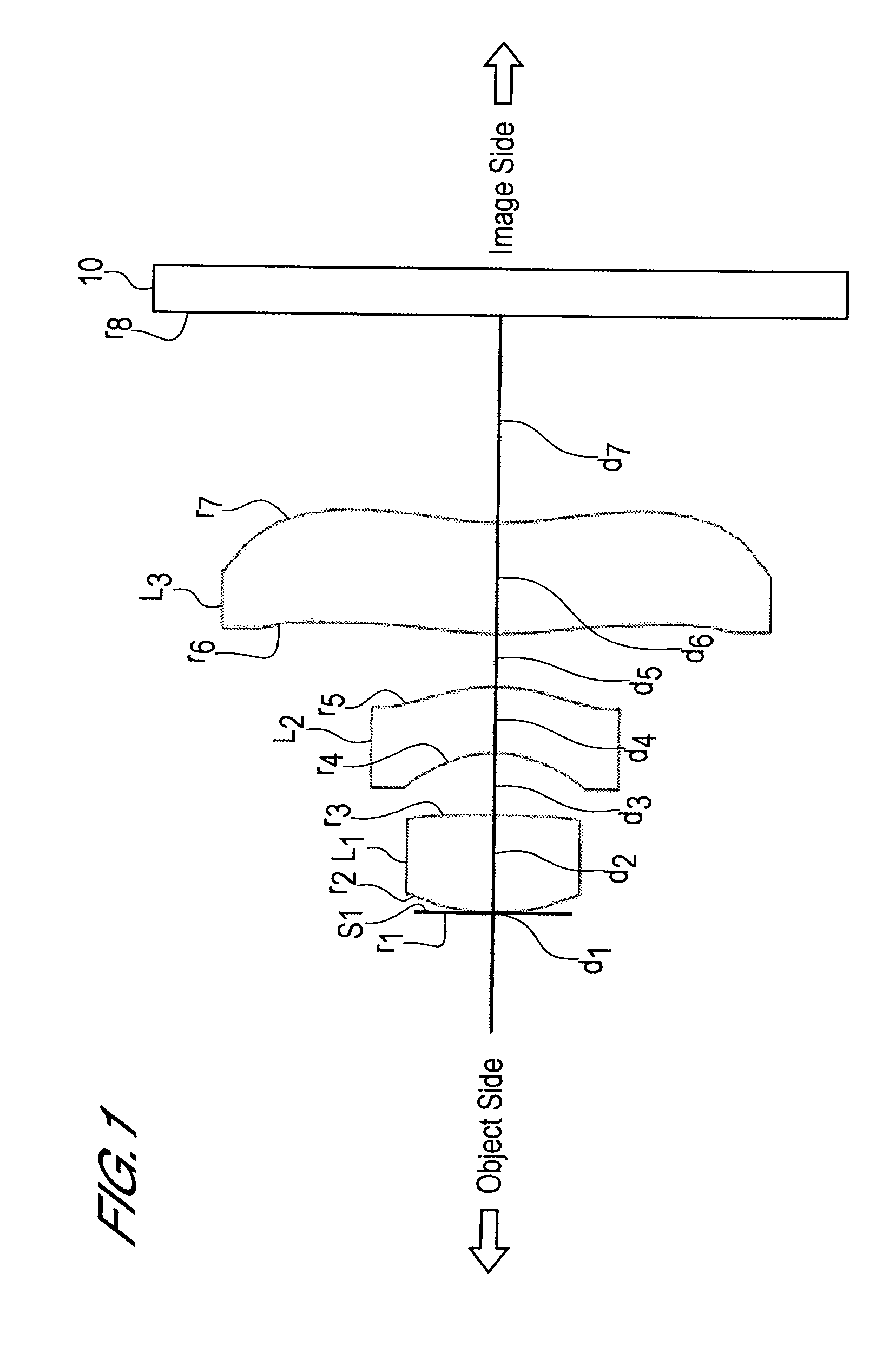
[0171]Zeonex E48R was used as the material of the first lens L1 and third lens L3, while fluorene polyester EP-4000 (EP-4000 is a product number of Mitsubishi Gas Chemical Co., Inc.) was used as the material of the second lens L2.

[0172](A) The object-side radius of curvature r2 of the first lens L1 is r2=0.356 mm.

[0173](B) The image-side radius of curvature r3 of the first lens L1 is r3=−17.782 mm.

[0174](C) The interval D along the optical axis between the second lens L2 and the third lens L3 is D (=d5)=0.1000 mm.

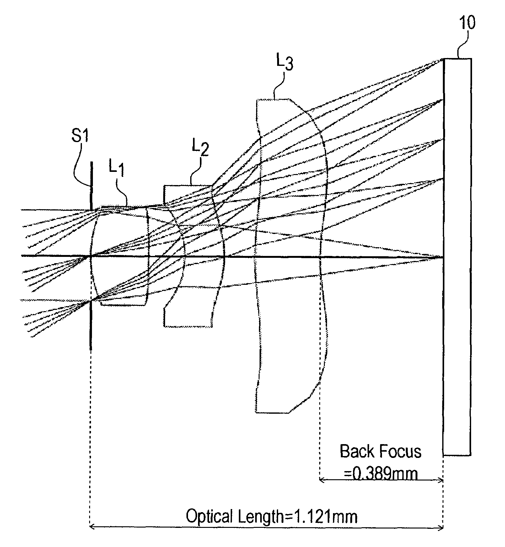
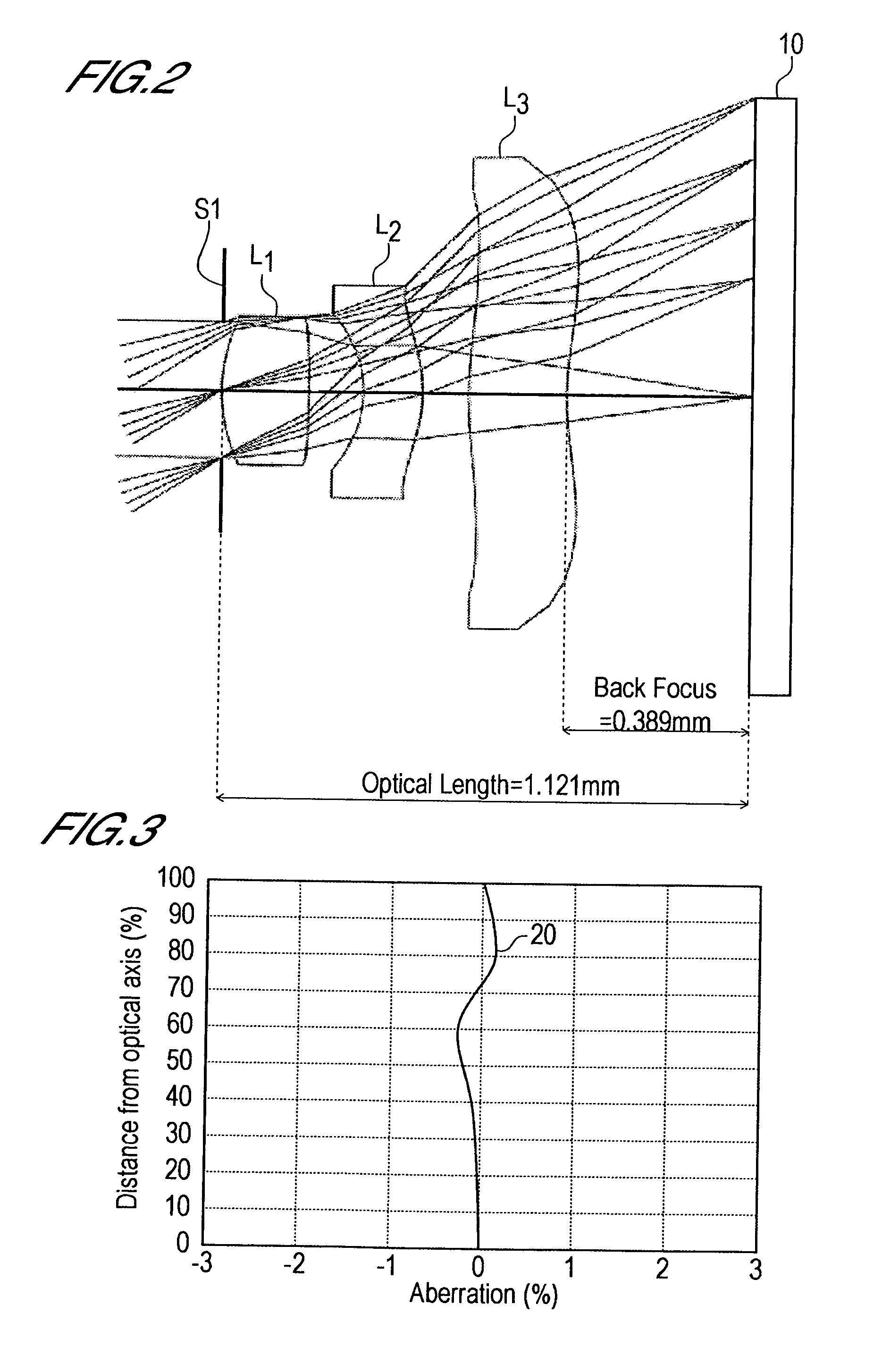
[0175](D) The optical length L is L=1.121 mm.

[0176](E) The image height (length of the diagonal line in the rectangular light-receiving area) 2Y is 2Y=2×0.64=1.28 mm.

[0177](F) The focal length f1 of the first lens L1 is f1=0.66 mm.

[0178]Hence:

|r2 / r3|=10.356 / −17.782|=0.020,  (1-1)

D / f=0.1000 / 1.00=0.1000,  (1-2)

L / 2Y=1.121 / 1.28=0.876, and  (1-3)

f1 / f=0.66 / 1.00=0.66.  (1-4)

[0179]Hence the lens system of the first Embodiment satisfies each of the following condition equations (1-1...

second embodiment

[0188]ZEONEX E48R was used as the material of the first lens L1 and third lens L3, and polycarbonate was used as the material of the second lens L2.

[0189](A) The object-side radius of curvature r2 of the first lens L1 is r2=0.356 mm.

[0190](B) The image-side radius of curvature r3 of the first lens L1 is r3=−17.782 mm.

[0191](C) The interval D along the optical axis between the second lens L2 and the third lens L3 is D (=d5)=0.1000 mm.

[0192](D) The optical length L is L=1.119 mm.

[0193](E) The image height (length of the diagonal line in the rectangular light-receiving area) 2Y is 2Y=2×0.64=1.28 mm.

[0194](F) The focal length f1 of the first lens L1 is f1=0.66 mm.

[0195]Hence:

|r2 / r3|=|0.3561 / −17.782|=0.020,  (1-1)

D / f=0.1000 / 1.00=0.1000,  (1-2)

L / 2Y=1.119 / 1.28=0.874, and  (1-3)

f1 / f=0.66 / 1.00=0.66.  (1-4)

[0196]Hence the lens system of the second Embodiment satisfies each of the following condition equations (1-1) through (1-4).

0.01<|r2 / r3|<0.05  (1-1)

0.05<D / f≦0.1  (1-2)

0.6<L / 2Y<...

third embodiment

[0205]ZEONEX E48R was used as the material of the first lens L1 and third lens L3, and polycarbonate was used as the material of the second lens L2.

[0206](A) The object-side radius of curvature r2 of the first lens L1 is r2=0.356 mm.

[0207](B) The image-side radius of curvature r3 of the first lens L1 is r3=−8.887 mm.

[0208](C) The interval D along the optical axis between the second lens L2 and the third lens L3 is D (=d5)=0.08 mm.

[0209](D) The optical length L is L=1.092 mm.

[0210](E) The image height (length of the diagonal line in the rectangular light-receiving area) 2Y is 2Y=2×0.64=1.28 mm.

[0211](F) The focal length f1 of the first lens L1 is f1=0.65 mm.

[0212]Hence:

|r2 / r3|=|0.356 / −8.887|=0.04,  (1-1)

D / f=0.1000 / 1.00=0.08,  (1-2)

L / 2Y=1.092 / 1.28=0.8531, and  (1-3)

f1 / f=0.65 / 1.00=0.65.  (1-4)

[0213]Hence the lens system of the third Embodiment satisfies each of the following condition equations (1-1) through (1-4).

0.01<|r2 / r3|<0.05  (1-1)

0.05<D / f≦0.1  (1-2)

0.6<L / 2Y<0.9  (1-...


PUM


Abstract

A pickup lens is provided with various aberrations corrected satisfactorily, with a short optical length, and with a sufficient back focus secured.The configuration comprises an aperture diaphragm S1, first lens L1, second lens L2, and third lens L3, and is configured by arranging, in order from the object side to the image side, the aperture diaphragm, first lens, second lens, and third lens. The first lens is a lens having positive refractive power, with convex surfaces on the object side and on the image side. The second lens is a lens having negative refractive power, in a meniscus shape with the convex surface on the image side. The third lens is a lens having negative refractive power, in a meniscus shape with the convex surface on the object side. Both of the surfaces of the first lens are aspherical, both of the surfaces of the second lens are aspherical, and both of the surfaces of the third lens are aspherical.

Description

TECHNICAL FIELD[0001]The present invention relates to a pickup lens, and in particular relates to a pickup lens suitable for being mounted in the image input devices of portable telephone sets and personal computers, in digital cameras, CCD cameras for monitoring use, inspection devices, and similar, which use CCDs and CMOS (Complementary Metal Oxide Semiconductor) devices as image pickup elements.BACKGROUND ART[0002]It is necessary that the above described pickup lens have a short optical length, defined as the distance from the incidence plane on the object side of the pickup lens to the image formation plane (the pickup surface of the CCD or similar). That is, in lens design, measures are necessary to reduce the ratio of the optical length to the combined focal length of the pickup lens. Hereafter, a pickup lens with short optical length and small ratio of optical length to focal length may be called a compact lens.[0003]Taking a portable telephone set as an example, at the least...

Claims


Application Information

Patent Timeline
Patent Type & Authority Patents(United States)
IPC IPC(8): G02B13/18G02B9/12
CPCG02B9/12G02B13/0035G02B13/18G02B13/16
Inventor DO, SATOSHI
Owner SEIKOH GIKEN
Why Eureka
Try Eureka