Zoom lens and image pickup device

a pickup device and zoom lens technology, applied in the field of zoom lens and image pickup device, can solve the problems of low accuracy of aspherical surface correction of plastic aspherical lens in the first lens group, insufficient correction of aberrations, and inability to optimize the zoom lens, so as to achieve sufficient back focus, improve performance, and reduce size

Inactive Publication Date: 2010-09-21
SONY CORP
View PDF2 Cites 4 Cited by
  • Summary
  • Abstract
  • Description
  • Claims
  • Application Information

AI Technical Summary

Benefits of technology

[0010]It is desirable for a zoom lens and an image pickup device according to embodiments of the present invention to overcome the aforementioned problems, to increase performance and reduce size, and to provide sufficient back focus.
[0033]Therefore, in the image pickup device according to the embodiment of the present invention, it is possible to increase performance and reduce size, and to provide sufficient back focus.

Problems solved by technology

Therefore, the zoom lens is not optimized with respect to recent digitization, as a result of which the zoom lens is not designed for size reduction suitable for a specification provided for digitization.
In addition, in the zoom lens discussed in Patent Document 1, the effect of correcting aberrations by an aspherical surface of a plastic aspherical lens in the first lens group is low, as a result of which the aberrations are not sufficiently corrected.

Method used


Image

  • Zoom lens and image pickup device
  • Zoom lens and image pickup device
  • Zoom lens and image pickup device

Examples


first embodiment

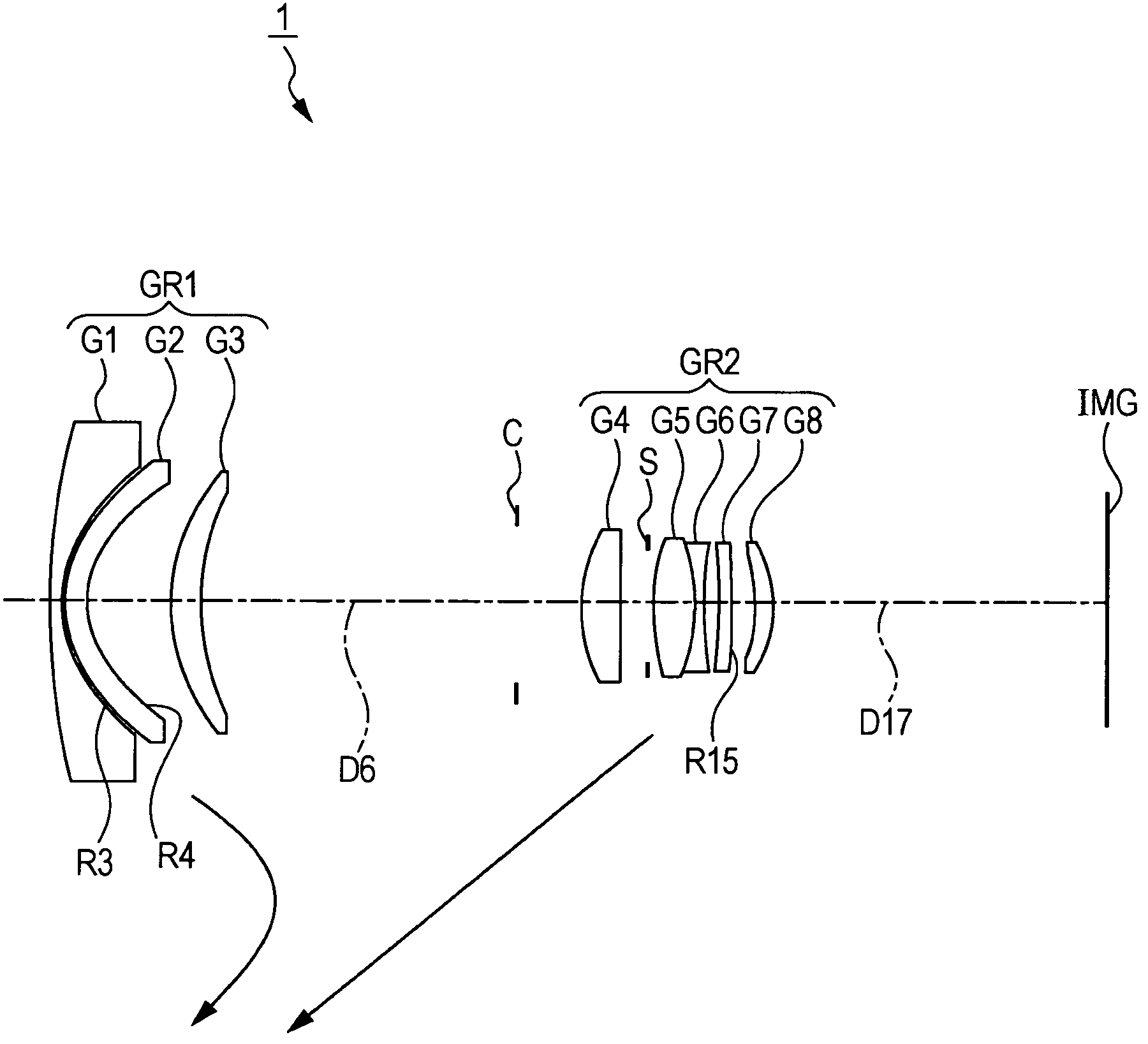
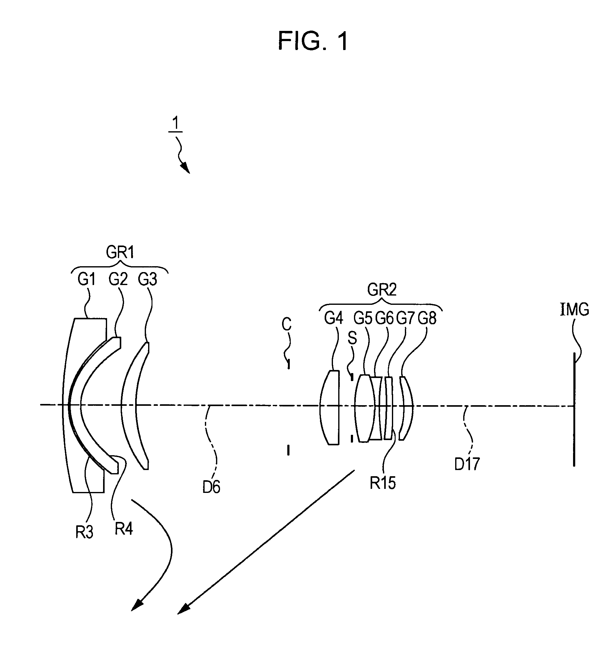
[0110]FIG. 1 shows a lens structure (in a wide-angle end state) of a zoom lens 1 according to the present invention. Each arrow indicates a path of movement of each lens group along the optical axis towards a telephoto end.

[0111]As shown in FIG. 1, the zoom lens 1 according to the first embodiment includes eight lenses.

[0112]In the zoom lens 1, when magnification is changed between the wide-angle end and the telephoto end, a first lens group GR1 and a second lens group GR2 are moved in an optical axis direction, and, when focusing is performed, the first lens group GR1 is moved in the optical axis direction.

[0113]In the zoom lens 1, the first lens group GR1 having a negative refractive power and the second lens group GR2 having a positive refractive power are disposed in that order from the object side to the image side. The first lens group GR1 and the second lens group GR2 each include at least one plastic aspherical lens.

[0114]In the first lens group GR1, a first lens G1 having a...

second embodiment

[0129]FIG. 5 shows a lens structure (in a wide-angle end state) of a zoom lens 2 according to the present invention. Each arrow indicates a path of movement of each lens group along the optical axis towards a telephoto end.

[0130]As shown in FIG. 5, the zoom lens 2 according to the second embodiment includes nine lenses.

[0131]In the zoom lens 2, when magnification is changed between the wide-angle end and the telephoto end, a first lens group GR1 and a second lens group GR2 are moved in an optical axis direction, and, when focusing is performed, the first lens group GR1 is moved in the optical axis direction.

[0132]In the zoom lens 2, the first lens group GR1 having a negative refractive power and the second lens group GR2 having a positive refractive power are disposed in that order from the object side to the image side. The first lens group GR1 and the second lens group GR2 each have at least one plastic aspherical lens.

[0133]In the first lens group GR1, a first lens G1 having a ne...

third embodiment

[0147]FIG. 9 shows a lens structure (in a wide-angle end state) of a zoom lens 3 according to the present invention. Each arrow indicates a path of movement of each lens group along the optical axis towards a telephoto end.

[0148]As shown in FIG. 9, the zoom lens 3 according to the third embodiment includes eight lenses.

[0149]In the zoom lens 3, when magnification is changed between the wide-angle end and the telephoto end, a first lens group GR1 and a second lens group GR2 are moved in an optical axis direction, and, when focusing is performed, the first lens group GR1 is moved in the optical axis direction.

[0150]In the zoom lens 3, the first lens group GR1 having a negative refractive power and the second lens group GR2 having a positive refractive power are disposed in that order from the object side to the image side. The first lens group GR1 and the second lens group GR2 each have at least one plastic aspherical lens.

[0151]In the first lens group GR1, a first lens G1 having a ne...


PUM


Abstract

A zoom lens includes a first lens group having negative refractive power and a second lens group having positive refractive power, each including at least one plastic aspherical lens. The zoom lens satisfies the following Conditional Expressions (1) and (2), (1) 0.40<fw / bkw<0.60; (2) 0.01<|(X1−X0) / h0|<0.022, where fw: focal length of the entire zoom lens in focus at infinity in a wide-angle end state; bkw: back focus when the entire zoom lens is in focus at infinity in the wide-angle end state; X1: thickness at an image-side effective diameter position of the plastic aspherical lens of the first lens group; X0: thickness at the center of the plastic aspherical lens of the first lens group; and h0: image-side effective radius of the plastic aspherical lens of the first lens group.

Description

BACKGROUND OF THE INVENTION[0001]1. Field of the Invention[0002]The present invention relates to a zoom lens and an image pickup device. More particularly, the present invention relates to the technical field of a zoom lens suitable for an interchangeable lens mountable to a digital single-lens reflex camera, having high performance, and capable of providing sufficient back focus; and to the technical field of an image pickup device including the zoom lens.[0003]2. Description of the Related Art[0004]In recent years, in an image pickup device, such as a still camera or a video camera, pixelation of an image pickup element is being increased due to a rapid progress in digitization, so that there is an increasing demand for a zoom lens adaptable to an increase in performance. In addition, there is a high demand for reducing costs, weight, and size, in addition to increasing performance.[0005]To meet such demands, in particular, in a zoom lens that covers a range from a wide-angle area...

Claims


Application Information

Patent Timeline
Patent Type & Authority Patents(United States)
IPC IPC(8): G02B15/14
CPCG02B15/177
Inventor IZUHARA, ISAMUNOSE, HIROMICHI
Owner SONY CORP
Why Eureka
Try Eureka