Projection lens and projection type display device using the same

a projection lens and display device technology, applied in the field of projection lenses and projection type display devices using the same, can solve the problems of lens unsuitability for application, performance degradation, and reduction of the number of constituent lenses

Inactive Publication Date: 2007-10-11
FUJI PHOTO OPTICAL CO LTD
View PDF7 Cites 4 Cited by
  • Summary
  • Abstract
  • Description
  • Claims
  • Application Information

AI Technical Summary

Benefits of technology

[0007]The invention has been made in view of the above circumstances, and provides an inexpensive projection lens that has a small number of constituent

Problems solved by technology

However, performance deterioration is caused when the number of constituent lenses is reduced simply.
However, since the lens disclosed in JP 2003-287676 A has a wide angle of view larger than 75 degree, such a lens is unsuitable for the application as the front projector that projects the image from the viewer side.
In other w

Method used


Image

  • Projection lens and projection type display device using the same
  • Projection lens and projection type display device using the same
  • Projection lens and projection type display device using the same

Examples


example 1

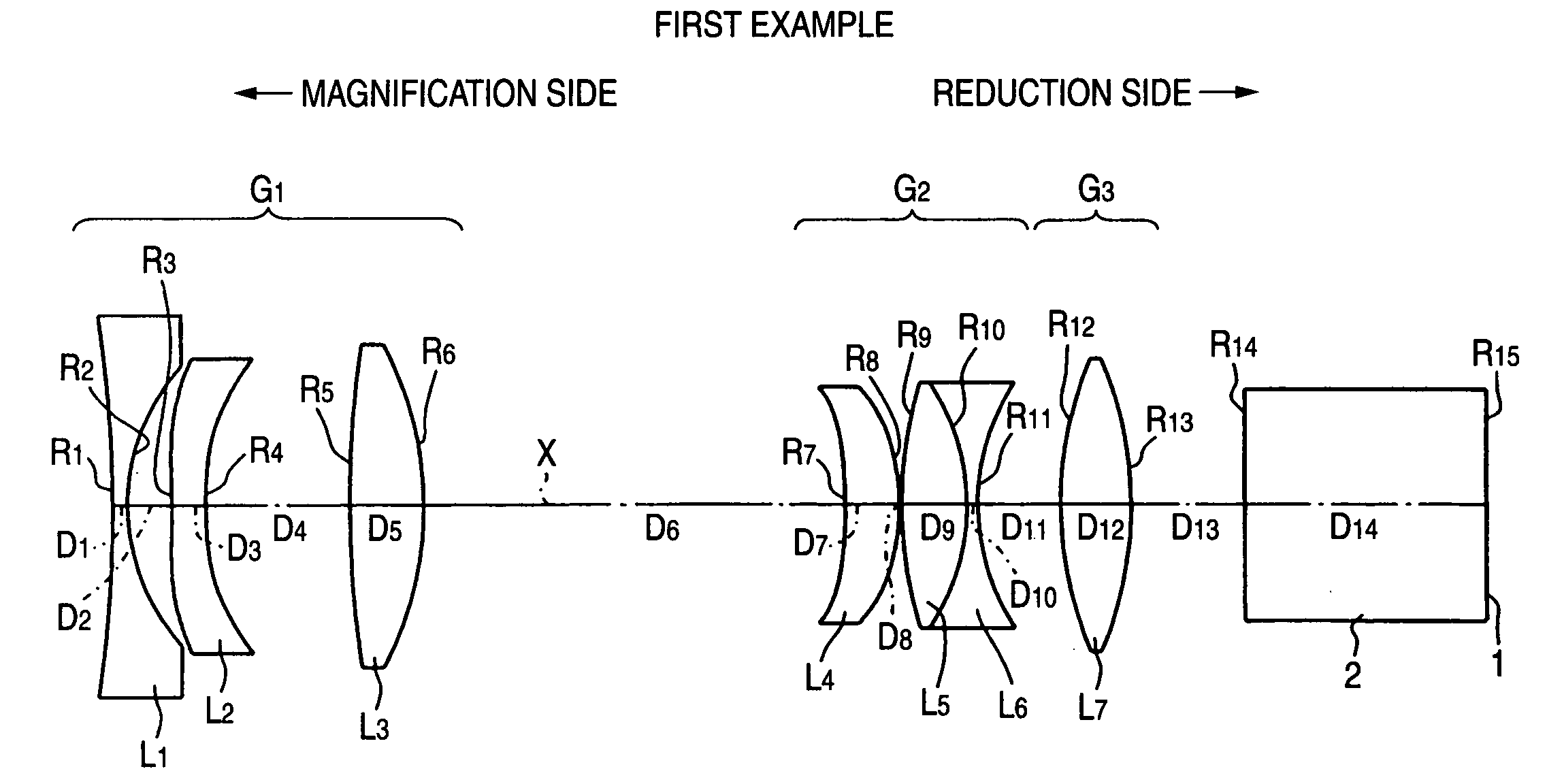
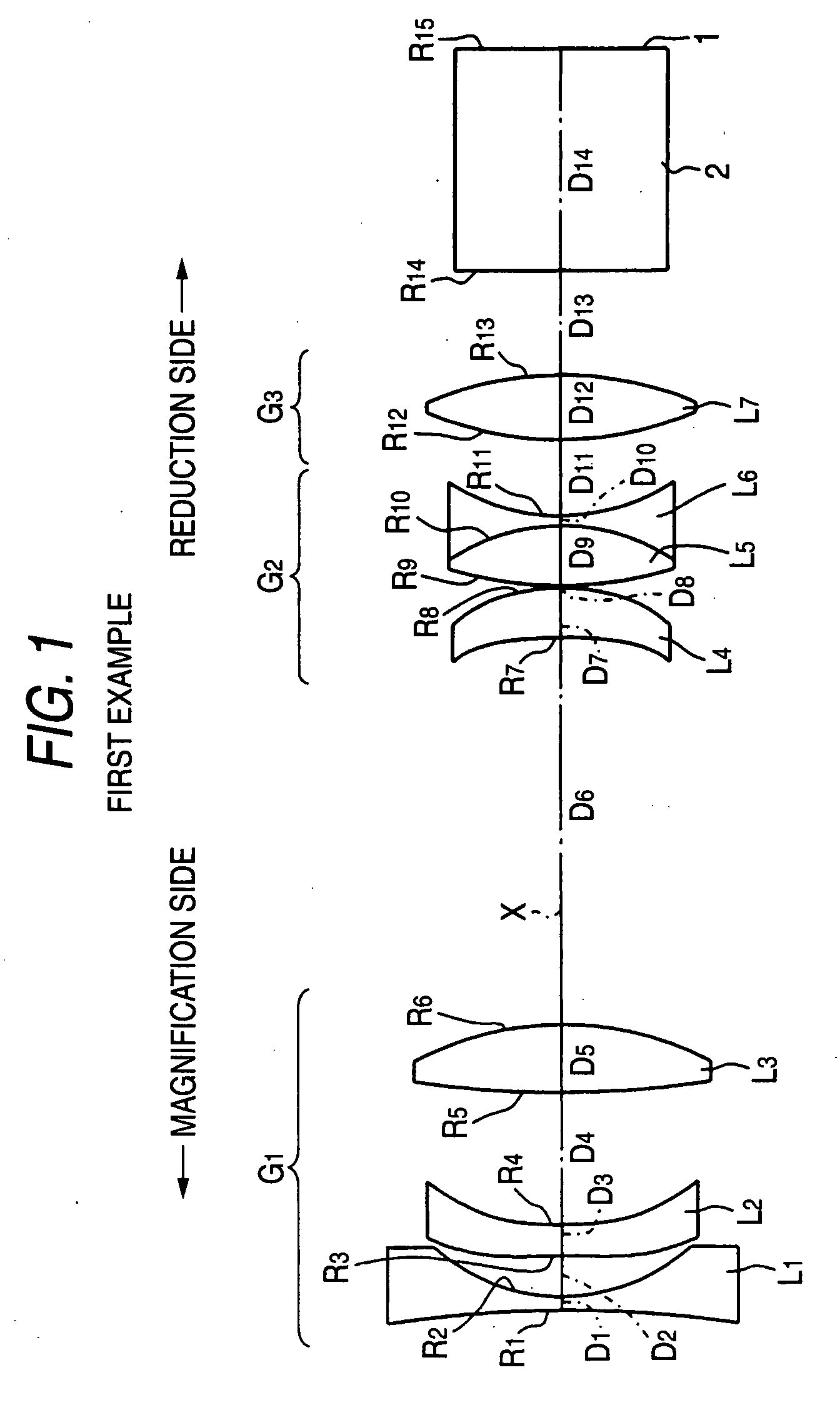
[0059]As described above, the projection lens according to the example 1 is configured as shown in FIG. 1. That is, in this projection lens, the first lens group G1 includes the first lens L1 which is a biconcave lens, the second lens L2 formed of a biconcave lens in the vicinity of the optical axis, and the third lens L3 formed of a biconvex lens in order from the magnification side. Also, the second lens group G2 includes the fourth lens L4 which is a positive meniscus lens whose concave surface is directed to the magnification side, and the cemented lens constructed by the fifth lens L5 formed of a biconvex lens and the sixth lens L6 formed of a biconcave lens. Also, the third lens group G3 includes the seventh lens L7 formed of a biconvex lens. In this case, the first lens L1 is formed of a glass lens.

[0060]In this example 1, radii R of curvature of respective lens surfaces (normalized under the assumption that a focal length of the entire lens system is set to 1; the same rule ...

example 2

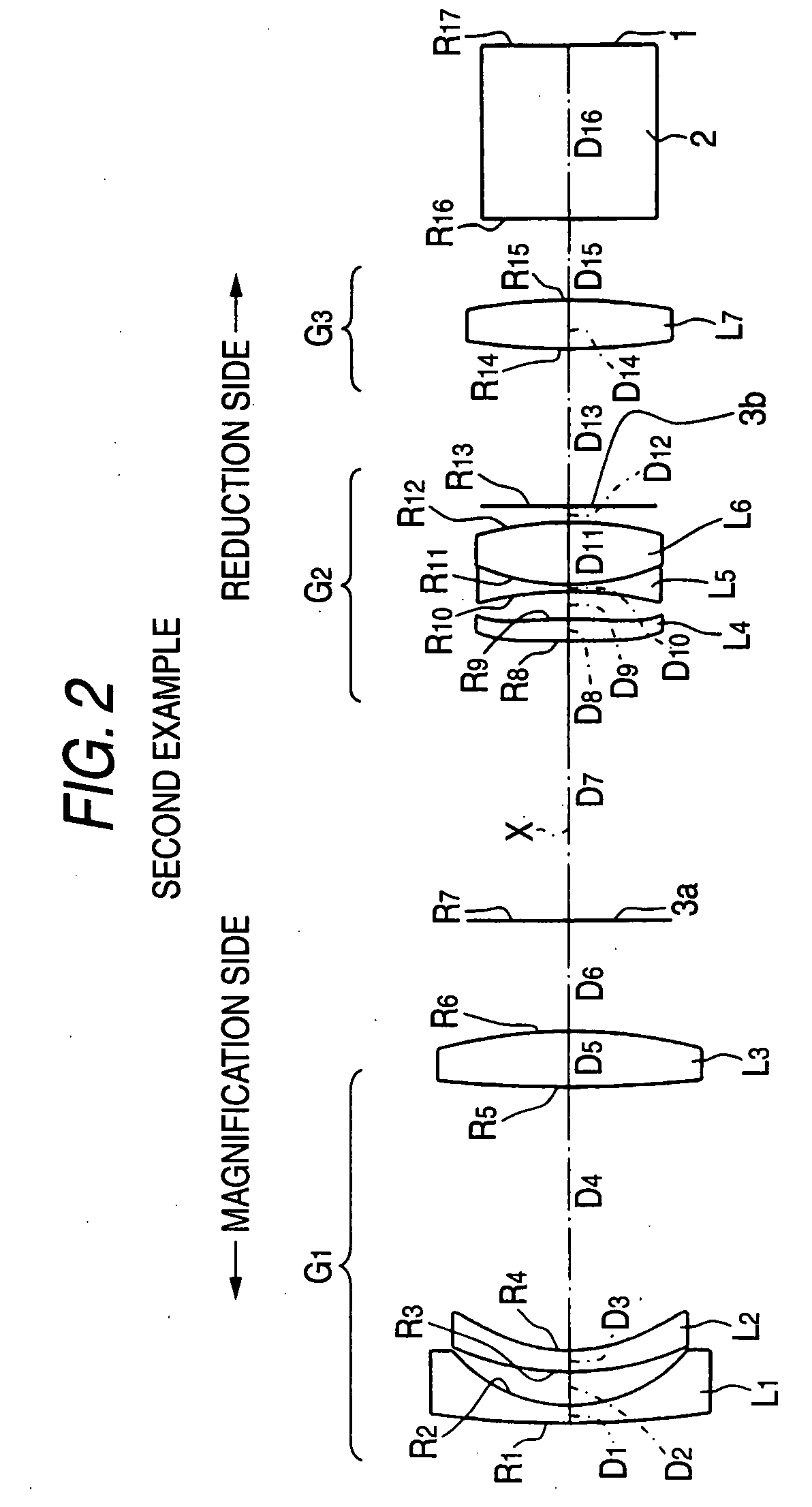
[0067]The schematic configuration of a projection lens according to the example 2 is shown in FIG. 2. The projection lens according to the example 2 is configured substantially similarly to that according to the example 1. A major difference from the example 1 is that the first lens L1 and the second lens L2 of the first lens group G1 are formed of a negative meniscus lens whose convex surface is directed to the magnification side, that the cemented lens of the second lens group G2 is constructed by the fifth lens L5 formed of a biconcave lens and the sixth lens L6 formed of a biconvex lens, and that masks 3a, 3b are disposed. However, it is not necessary to provide the masks. Also, a diaphragm may be employed as the mask. Positions of the masks 3a, 3b are not limited to those shown in FIG. 2, and setting positions of the masks 3a, 3b may be changed appropriately.

[0068]In this example 2, radii R of curvature of the respective lens surfaces, center thicknesses of the respective lense...

example 3

[0074]The schematic configuration of a projection lens according to the example 3 is shown in FIG. 3. The projection lens according to the example 3 is configured substantially similarly to that according to the example 1. A major difference from the example 1 is that the second lens L2 Of the first lens group G1 is formed of a negative meniscus lens whose convex surface is directed to the magnification side, that the second lens group G2 includes the cemented lens configured by the fourth lens L4 formed of a biconcave lens and the fifth lens L5 formed of a biconvex lens and the sixth lens L6 formed of a biconvex lens in the vicinity of the optical axis, and that a mask 3 is provided. However, it is not necessary to provide the mask 3, and a diaphragm may be employed as the mask 3. Also, a position of the mask 3 is not limited to that shown in FIG. 3, and a setting position of the mask 3 may be changed appropriately.

[0075]In this Example 3, radii R of curvature of the respective len...


PUM


Abstract

A projection lens includes, in order from a magnification side, a first lens group, a second lens group and a third lens group. The first lens group includes, in order from the magnification side, a negative lens whose lens made of a non-resin, a plastic lens at least one surface of which is aspheric and a positive lens. The second lens group includes a plastic lens at least one surface of which is aspheric, a positive lens and a negative lens. The third lens group includes a positive lens. The following conditional expressions are satisfied.
1.0<Bf/f≦1.8
2.0<f1/f
2.0<f2/f
where Bf denotes a air-conversion back focus of the entire system, f denotes a focal length of the entire system, f1 denotes a focal length of the first lens group and f2 denotes a focal length of the second lens group.

Description

BACKGROUND OF THE INVENTION[0001]1. Technical Field[0002]The invention relates to a projection lens installed into a projection type display device and a projection type display device and, more particularly, a projection lens used in a projector system into which a light valve such as a transmission type liquid crystal, a reflection type liquid crystal or DMD (Digital Micromirror Device) is installed.[0003]2. Description of the Related Art[0004]A spreading speed of the recent projector is rapid, and the inexpensive projector is requested. Also, in respond to this request, the lens having a small number of constituent lenses is demanded of the projection lens used in the projector. However, performance deterioration is caused when the number of constituent lenses is reduced simply. In order to compensate such performance deterioration, the development of the lens having a small number of constituent lenses by using a lot of aspheric surfaces, and the like is proceeding. Such project...

Claims


Application Information

Patent Timeline
IPC IPC(8): G02B15/14
CPCG02B13/16
Inventor YAMAMOTO, CHIKARAYAMADA, HIROSHI
Owner FUJI PHOTO OPTICAL CO LTD
Why Eureka
Try Eureka