Adjustable orientation angle multiple suction cup mountable spot mirror

a mirror and angle adjustment technology, applied in the field of mirrors, can solve the problem of not being able to position one's face sufficiently close to an existing flat mirror,

Active Publication Date: 2014-12-09
ZADRO INC
View PDF8 Cites 26 Cited by
  • Summary
  • Abstract
  • Description
  • Claims
  • Application Information

AI Technical Summary

Benefits of technology

[0020]In a preferred embodiment of the invention, multiple concentric rows of suction cups which are coaxial with a centrally located suction cup are provided. This arrangement enables the spot mirror to be releasably attached to a flat surface and adjusted over a wide range of elevation and azimuth angles relative to the support surface, and to be releasably re-fastened at a new adjustable angle by merely pressing upon the front of the mirror at a location offset from the center of the mirror towards the new desired orientation. In a modification of the preferred embodiment, the central suction cup is eliminated, and the mirror adhered in parallel to a flat surface by one or more pairs of resilient suction cups located equidistant from the center of the mirror.

Problems solved by technology

In some circumstances, however, it is not convenient to position one's face sufficiently close to an existing flat mirror to provide an image of the face which is sufficiently large to enable a desired personal grooming task to be easily performed.

Method used


Image

  • Adjustable orientation angle multiple suction cup mountable spot mirror
  • Adjustable orientation angle multiple suction cup mountable spot mirror
  • Adjustable orientation angle multiple suction cup mountable spot mirror

Examples


Embodiment Construction

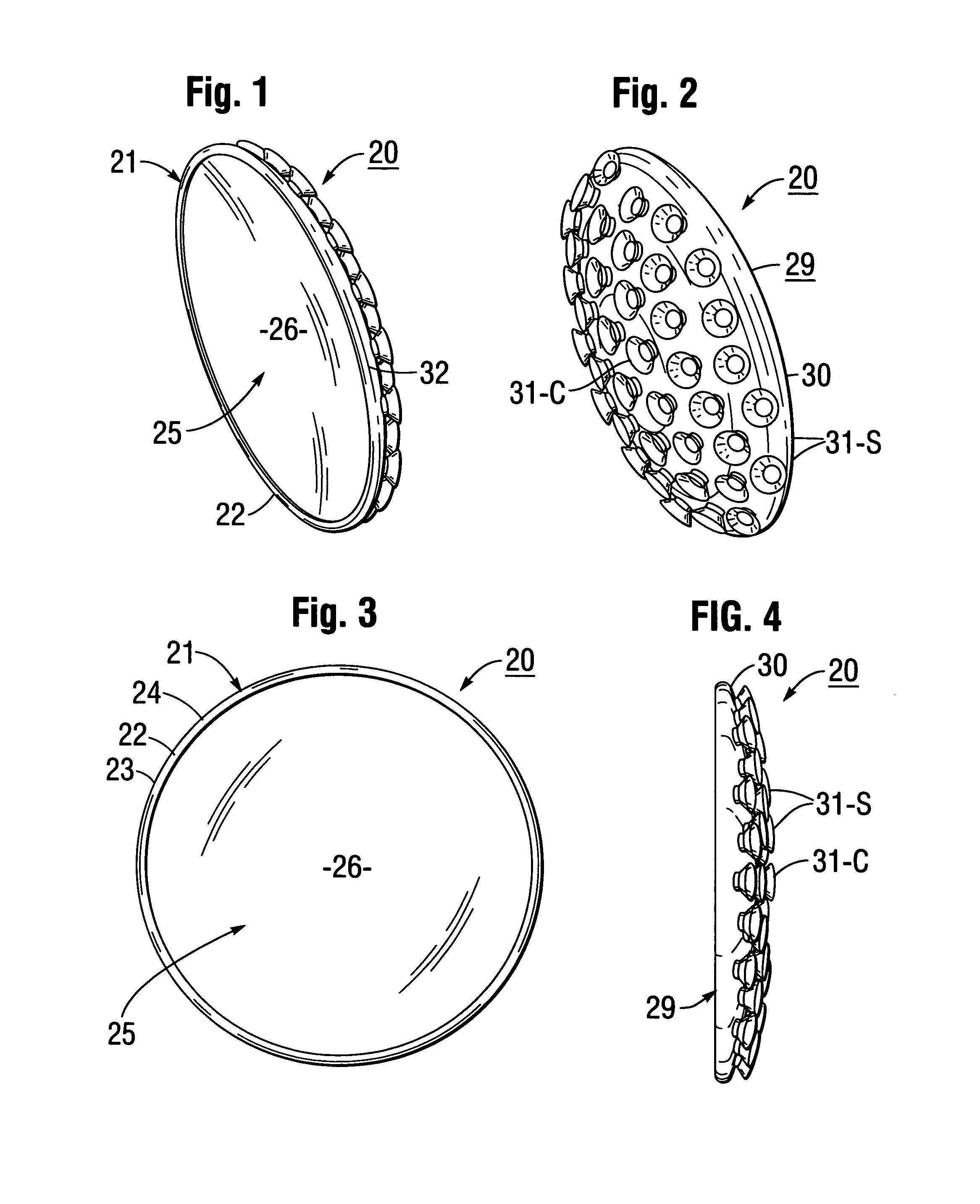
[0037]FIGS. 1-14 illustrate a preferred embodiment of an adjustable orientation angle multiple suction cup-mountable mirror according to the present invention.

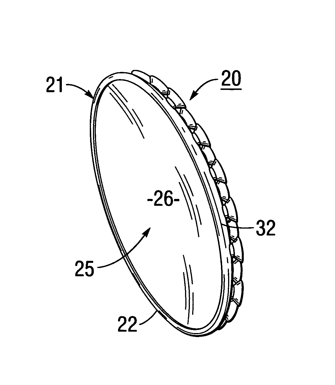
[0038]Referring to FIGS. 1-5, an adjustable orientation angle suction cup-mountable spot mirror 20 according to the present invention is shown to include a circular frame 21 which is circumscribed by a peripheral annular ring-shaped bezel ring 22. Bezel ring 22 has an outer longitudinally disposed side wall 23 which has a peripheral flange 24 that protrudes perpendicularly and radially inwardly therefrom to retain therebehind a reflective mirror 25.

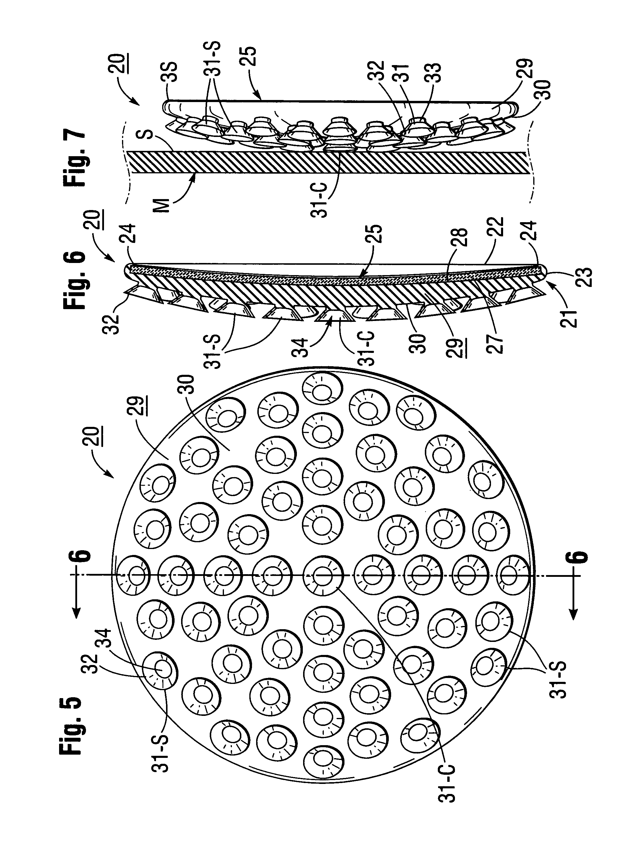
[0039]As shown in FIG. 6, mirror 25 has a forward facing reflective surface 26, and a rear surface 27 which is seated on the front surface 28 of a body 29 of frame 21. In the preferred embodiment, reflective surface 26 of mirror 25 is rearwardly or inwardly concave, thus providing magnified images of objects located in front of the mirror.

[0040]As shown in FIG. 3, spot mirror 20 pre...


PUM


Abstract

A magnifying spot mirror releasably attachable to a flat surface includes a circular concave mirror plate mounted on the front surface of a lenticular-shaped support body which has a convex, arcuately curved rear surface from which protrude satellite suction cups that have circular bases which lie in a convex plane and are radially spaced equidistant from the center of the support body and an optional center suction cup. Applying finger pressure to the center of the mirror causes a pair of centrally located suction cups and/or the optional center cup to hermetically grip a flat surface with the mirror parallel to the surface. Pressing on the mirror at a location offset from the center exerts a tensional unsealing force on radially inwardly located suction cups, and compressional sealing forces on outer satellite suction cups, thus re-positioning the mirror at a different orientation angle.

Description

BACKGROUND OF THE INVENTION[0001]A. Field of the Invention[0002]The present invention relates to mirrors of the type used to facilitate performance of personal care functions such as shaving, applying cosmetics, and the like. More particularly, the invention relates to a novel mirror which includes a frame that is releasably attachable to a flat surface such as that of a larger flat mirror or shower wall, at adjustable inclination angles relative to the mounting surface.[0003]B. Description of Background Art[0004]Some aspects of a person's appearance are best attended to by observing his or her image in a relatively large “wide angle” mirror, which has unity or “l×” magnification, such as a full length wall mirror, a dresser mirror, or a bathroom mirror mounted on a wall or cabinet. On the other hand, certain personal grooming functions such as shaving, applying cosmetics and the like are generally more easily performed while viewing a larger image of one's face, which can be provid...

Claims


Application Information

Patent Timeline
Patent Type & Authority Patents(United States)
IPC IPC(8): A47G1/16G02B7/182A47F1/14B60R1/02
CPCG02B7/182A45D42/14
Inventor ZADRO, ZLATKO
Owner ZADRO INC
Why Eureka
Try Eureka