Display device with narrowed frame border and manufacturing method thereof

a display device and frame border technology, applied in the field of display devices, can solve the problems of poor appearance, unsatisfactory size reduction effect of the first approach, and the current approach still has some problems, so as to achieve the effect of narrowing the size of the display device and increasing the stability of the integral structur

Active Publication Date: 2014-12-09
AU OPTRONICS CORP
View PDF13 Cites 3 Cited by
  • Summary
  • Abstract
  • Description
  • Claims
  • Application Information

AI Technical Summary

Benefits of technology

[0007]It is another object of the present invention to provide a display device having a frame border width equal to that of the display panel so as to achieve a smaller volume while maintaining the original structural strength.
[0009]The display device includes a backlight module, an optical film, and a display panel. The backlight module includes an outer frame and a light source module. The outer frame has a bottom plate and a sidewall connected to one side of the bottom plate. The light source module is disposed in the outer frame and located on an inner side of the sidewall. The optical film is disposed above the backlight module and covers the light source module. The edge of the optical film protrudes outside the sidewall and is bent to partially overlap the sidewall. The display panel is disposed on the surface of the optical film opposite to the backlight module. After the optical film and the outer frame are combined, the stability of the integral structure will be increased by the structural strength provided by the optical film, and the size of the display device can be narrowed while the backlight module is protected by the outer frame.

Problems solved by technology

However, the current approaches still have some problems described as follows.
The overly wide frame border width L1 will cause a poor appearance.
Moreover, the size reduction effect provided by the first approach mentioned above is still not perfect.

Method used


Image

  • Display device with narrowed frame border and manufacturing method thereof
  • Display device with narrowed frame border and manufacturing method thereof
  • Display device with narrowed frame border and manufacturing method thereof

Examples


Embodiment Construction

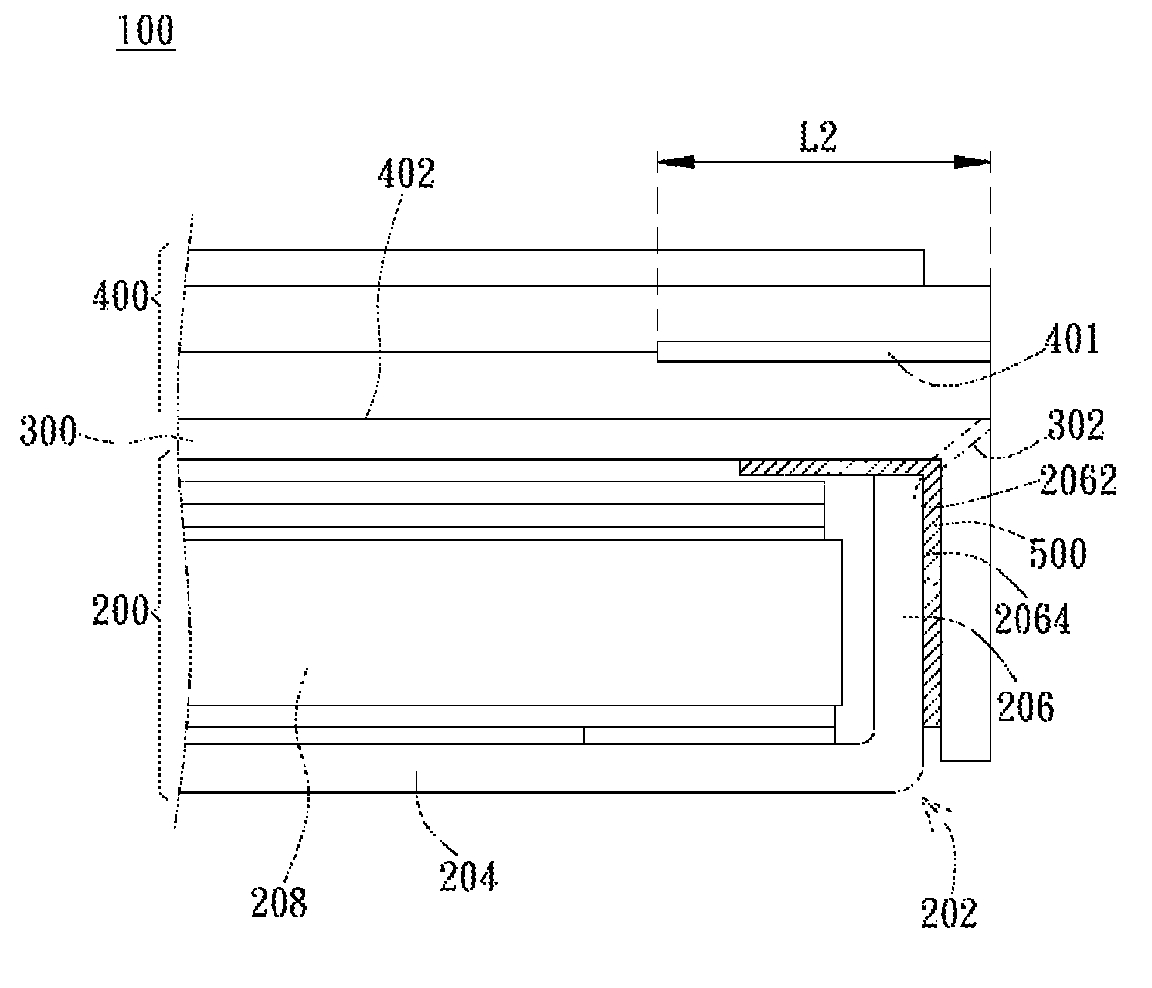
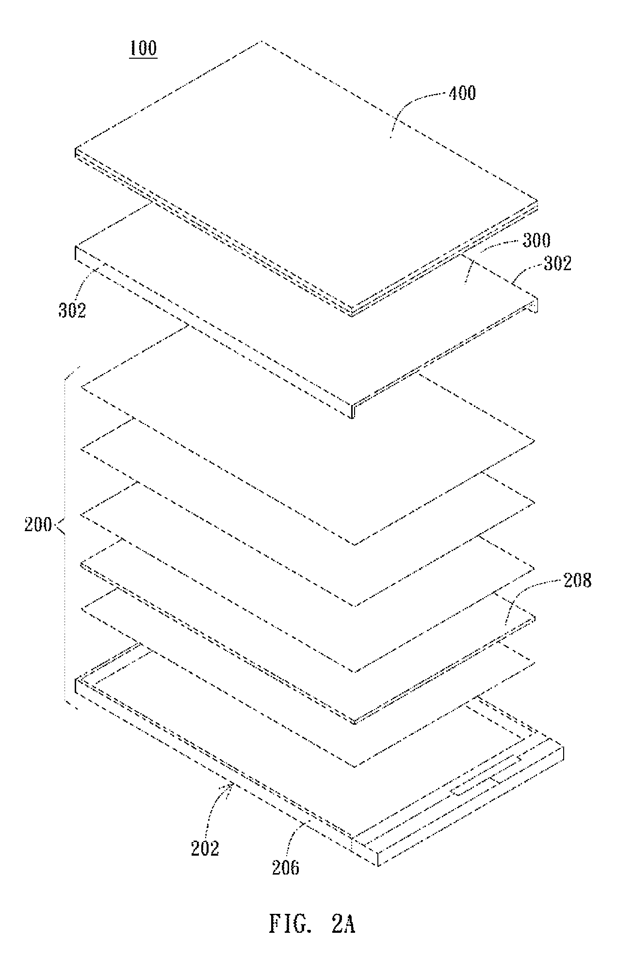
[0016]FIG. 2A and FIG. 2B are schematic views of the display device of the present invention. The display device 100 of the present invention includes a backlight module 200, an optical film 300, and a display panel 400. The backlight module 200 includes an outer frame 202 and a light source module 208. The outer frame 202 is preferably made of metal materials or may be made of polymer composite materials. The outer frame 202 has a bottom plate 204 and a sidewall 206 connected to one side of the bottom plate 204. The bottom plate 204 may be a solid plate or a partially hollow-carved plate based on design requirements. The sidewall 206 is disposed on least one side of the bottom plate 204 and preferably on two corresponding sides of the bottom plate 204. The light source module 208 is disposed in the outer frame 202 and located on an inner side of the sidewall 206. In a preferred embodiment, the light source module 208 is an edge type light source module including a light guide plate...


PUM


Abstract

A display device with narrowed frame border and a manufacturing method thereof are provided. The display device includes a backlight module, an optical film, and a display panel. The backlight module includes an outer frame and a light source module. The outer frame has a bottom plate and a sidewall connected to the bottom plate, and the light source module is disposed in the outer frame near the sidewall. The optical film is disposed on the backlight module and covers the light source module. One side of the optical film protrudes outside from the sidewall and is bent to attach a portion of the sidewall. The display panel is disposed on the optical film opposite to the backlight module.

Description

BACKGROUND OF THE INVENTION[0001]1. Field of the Invention[0002]The present invention relates to a display device; particularly, the present invention relates to a display device with a narrower frame border width.[0003]2. Description of the Prior Art[0004]In applications of display device, especially for the hand-held display device, getting a narrower sized frame border for the display device is a main subject of product improvement to promote the quality of appearance and minimize the volume of modules. The method of minimizing the size of the display device usually minimizes or eliminates component units at the periphery according to requirements. However, the current approaches still have some problems described as follows.[0005]FIG. 1 is a schematic view of the traditional display device. As shown in FIG. 1, the periphery of the traditional display device 10 mainly includes a frame 20 and a back plate 30, and the back plate 30 covers the frame 20 to protect the traditional dis...

Claims


Application Information

Patent Timeline
Patent Type & Authority Patents(United States)
IPC IPC(8): G09F13/04F21V8/00F21V9/14
CPCG09F13/04F21V9/14Y10T156/1034
Inventor WU, CHIA-HAONG, DARMAN
Owner AU OPTRONICS CORP
Why Eureka
Try Eureka