Expandable interbody implant and method

a technology of interbody implants and implants, which is applied in the field of expandable interbody implants, can solve the problems of predisposing the implant to subsidence and lessening the corrective support applied to the spine, and achieve the effect of improving regional lordosis and global sagittal balan

Active Publication Date: 2014-12-09
POULOS NICHOLAS
View PDF27 Cites 14 Cited by
  • Summary
  • Abstract
  • Description
  • Claims
  • Application Information

AI Technical Summary

Benefits of technology

[0009]Still further, the present disclosure relates to such an expandable (variable height) or non-expandable (fixed height) disc prosthesis that may have angled upper and lower surfaces engageable with the adjacent vertebrae bodies so as to introduce a predetermined degree of lordosis thereby to better reconstruct the spine by introducing segmental lordosis and improving regional lordosis and global sagittal balance. It is also understood that 0° or parallel surfaced implants maybe an appropriate choice dictated by intraoperative findings and surgical anatomy.

Problems solved by technology

However, these prior spacers were typically of a predetermined thickness and thus it was difficult to size the thickness of the spacer to result in the desired amount of distraction between the vertebrae bodies in order to achieve the desired amount of distraction between the adjacent vertebra bodies.
However, these adjustable fusion devices rely on cams and other complicated mechanisms for adjustment purposes.
Otherwise, an implant having parallel upper and lower surfaces used in a disc space having, for example, 8 degrees of in situ lordosis would result in only part of the implant contacting its respective vertebrae bodies and thereby lessening the corrective support applied to the spine and thus predisposing the implant to subsidence.

Method used


Image

  • Expandable interbody implant and method
  • Expandable interbody implant and method
  • Expandable interbody implant and method

Examples


first embodiment

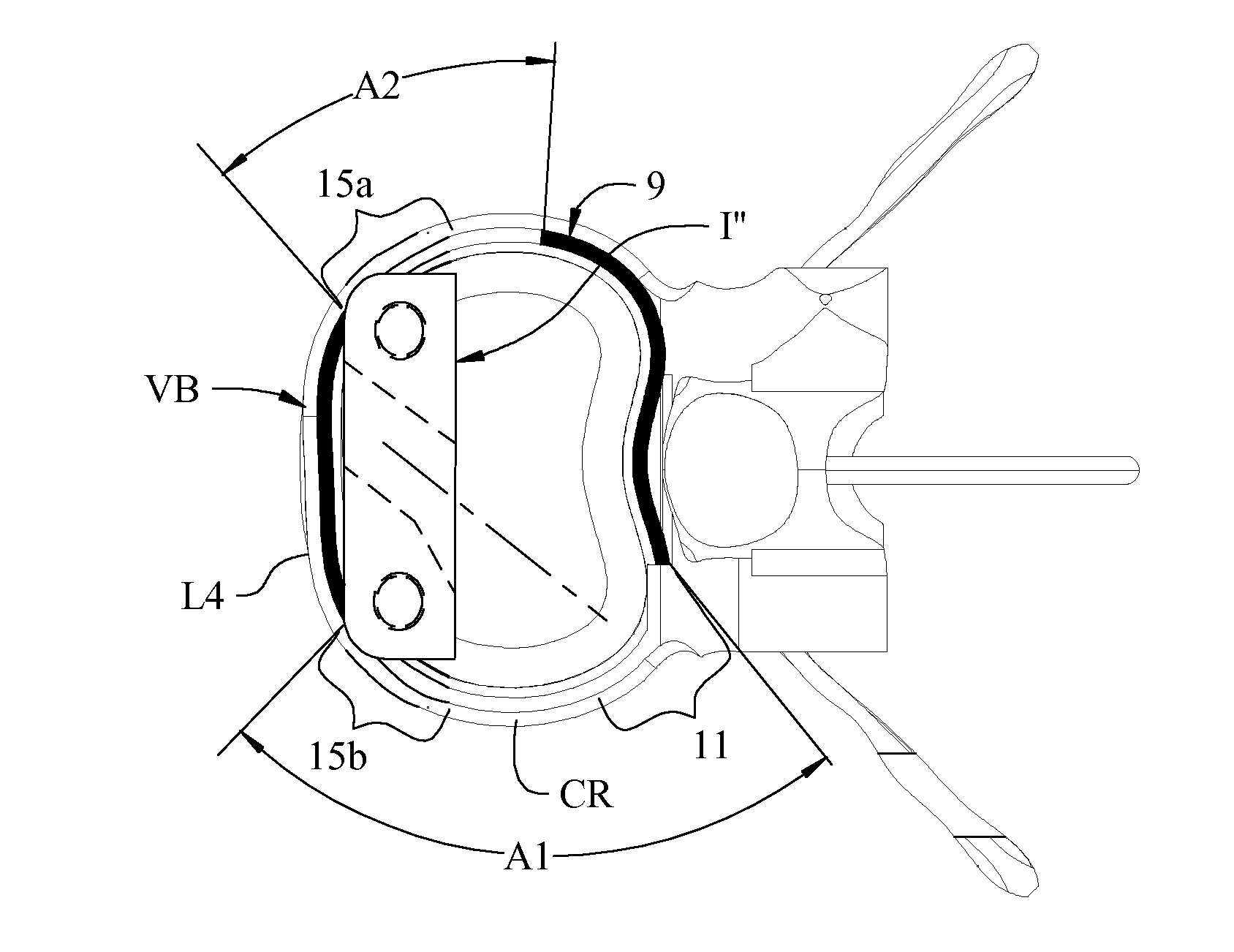
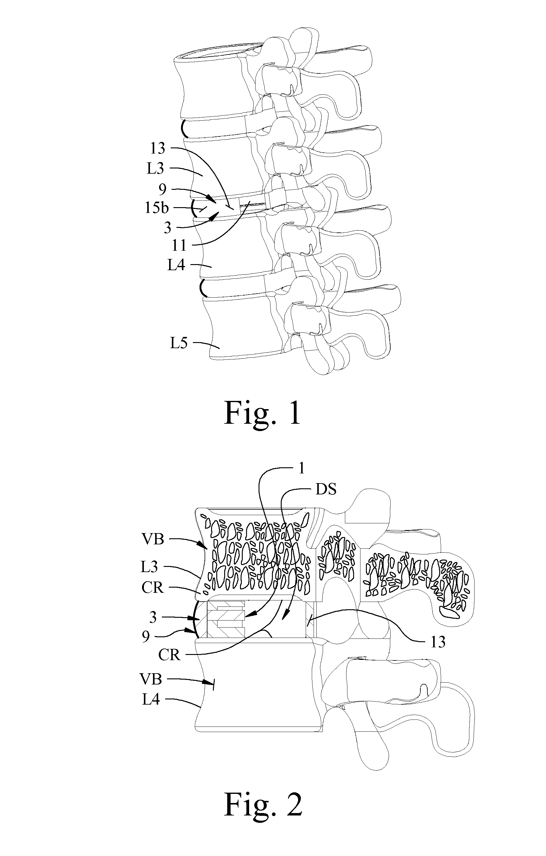
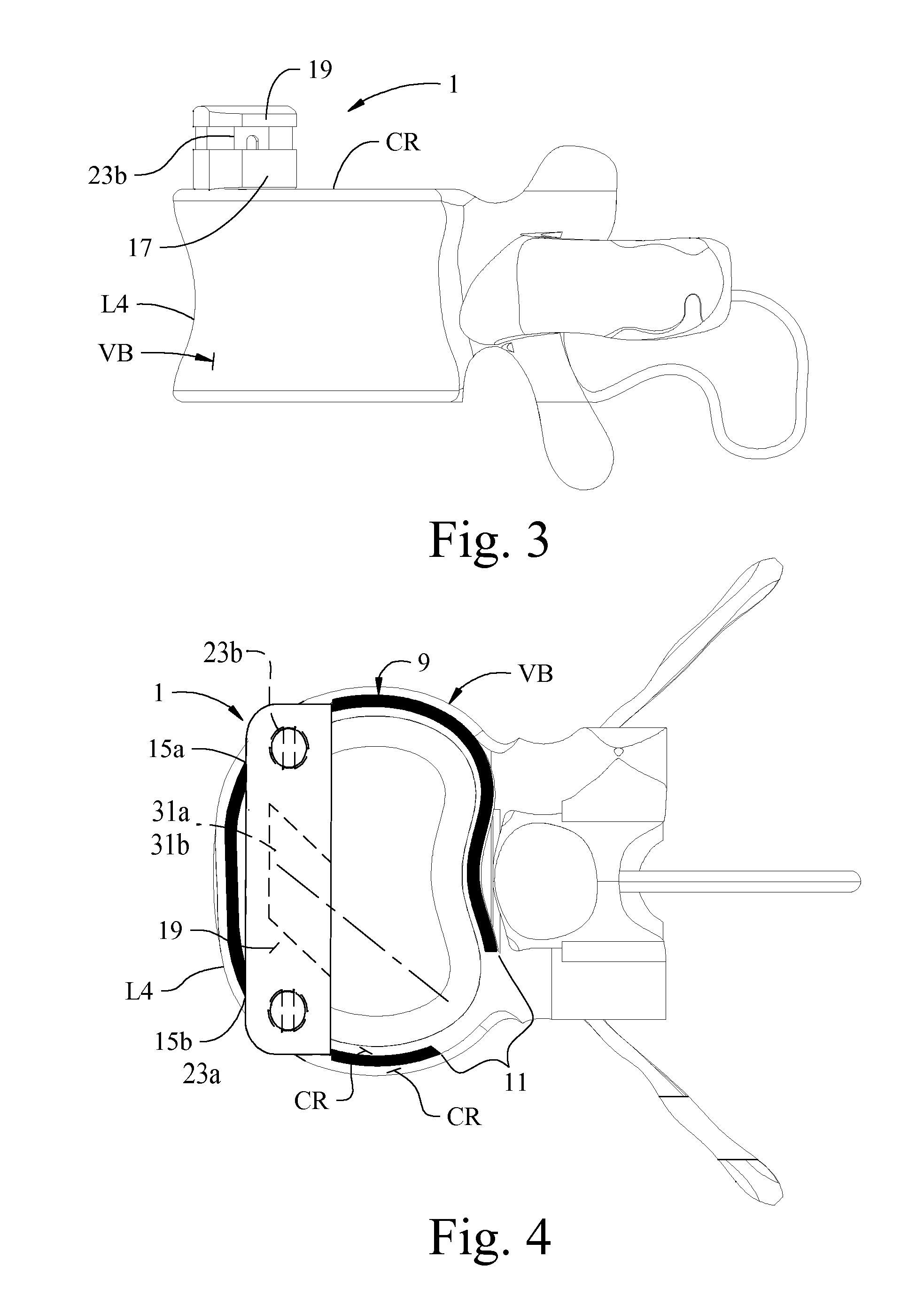
[0101]Referring now to the drawings and particularly to FIGS. 1-4C, a lumbar disc implant device of the present disclosure is generally indicated at 1 (see FIG. 2), and is shown in its intended environment installed within the disc space DS between two adjacent human vertebrae to be fused together. Oftentimes the intervertebral disc 3 between two adjacent vertebrae (e.g., between lumbar vertebrae L3 and L4, or between lumbar vertebrae L4 and L5) may become degenerated and mechanically incompetent with subsequent loss of height between the adjacent vertebrae with resultant pain and loss of motion. It has become common practice to surgically reconstruct the degenerated disc 3 between the opposing surfaces of the vertebrae bodies and to insert a structural implant within the disc space between the vertebrae so as to space the vertebrae apart a desired distance thus restoring disc space height, and to bear normal biomechanical loads in the spine until a solid spinal fusion occurs. As is...

second embodiment

[0130]Referring now to FIGS. 19-41, the implant of this disclosure is indicated in its entirety by reference character 101. The “primed” reference characters shown in FIGS. 19-30 ranging between 1 and 43 indicate parts having substantially the same construction and function as the parts identified by these reference characters 1-43 in FIGS. 1-18. However, some of these components have been modified to carry out a somewhat different function, as will be described.

[0131]As shown in FIG. 19, lower body member 17′ has a tab 103 extending upwardly from the inner surface of one of the body members, for example, the lower body member along the anterior end thereof. This tab 103 extends up from the upper surface of the lower body member a distance sufficient so as to be at least partially slidingly received in a corresponding groove 105 formed in the anterior wall 107 of the other body member, for example, upper body member 19′ when a spacer 35′ is received within space 21′ between the uppe...


PUM


Abstract

An intervertebral implant that can be surgically introduced between adjacent vertebrae and expanded in situ to occupy an optimal space between the vertebrae. The implant is inserted into the evacuated disc space obliquely and then oriented so as to extend laterally across the anterior adjacent vertebrae with its outer ends of the implant supported by the cortical rims on the opposite sides of the vertebrae. The implant has two body members with a space therebetween so the implant may be then distracted and a spacer of predetermined thickness that may be inserted within the space between the body members so as to maintain a desired amount of distraction. The upper and lower surfaces of the implant may have a desired lordotic angle. A method of using an implant is disclosed which permits endoscopic visualization of the disc space.

Description

CROSS-REFERENCE TO RELATED APPLICATIONS[0001]This application is a continuation-in-part and claims priority to U.S. Provisional Patent Application No. 61 / 251,002, filed Oct. 13, 2009; to U.S. Provisional Patent Application No. 61 / 356,851, filed Jun. 21, 2010; to U.S. patent application Ser. No. 12 / 899,625, filed Oct. 7, 2010; to U.S. patent application Ser. No. 13 / 030,618, filed Feb. 18, 2011; and to U.S. Provisional Patent Application No. 61 / 610,198, filed on Mar. 13, 2012. These prior applications are all incorporated herein by reference in their entirety.STATEMENT REGARDING FEDERALLY SPONSORED RESEARCH OR DEVELOPMENT[0002]Not Applicable.BACKGROUND OF THE DISCLOSURE[0003]This disclosure relates to intervertebral disc prostheses, and more particularly to an intervertebral disc prosthesis that can be surgically introduced between adjacent vertebral bodies, preferably between lumbar vertebrae, and adjusted or expanded in situ to occupy an optimal or desired space between the vertebra...

Claims


Application Information

Patent Timeline
Patent Type & Authority Patents(United States)
IPC IPC(8): A61F2/30A61B17/00A61B17/02A61F2/46A61F2/44
CPCA61F2/4465A61F2002/30565A61F2002/30357A61F2/447A61F2/4684A61F2002/3008A61F2002/30611A61F2002/30598A61F2310/00131A61F2002/30616A61F2002/30607A61F2310/00023A61F2002/30596A61F2002/30736A61F2002/30556A61F2002/30579A61B2017/00261A61F2310/00017A61F2002/4475A61F2/442A61F2002/30518A61F2/4611A61F2002/30784A61F2002/30504A61B2017/0256A61F2220/0033A61F2002/30604A61F2002/305A61F2002/30594A61F2002/30593A61B17/025A61F2/4455
Inventor POULOS, NICHOLAS
Owner POULOS NICHOLAS
Why Eureka
Try Eureka