Coupler knuckle

a technology of couplers and knuckles, which is applied in the direction of railway couplings, railway coupling accessories, railway components, etc., can solve the problems of coupler-knuckle assembly design that does not consistently meet, damage or break the pin or assembly, and the coupler-knuckle assembly is not consistent, so as to prevent bending and breakage of the knuckle pin. , the effect of reducing fatigu

Active Publication Date: 2014-12-16
AMSTED RAIL CO INC
View PDF9 Cites 6 Cited by
  • Summary
  • Abstract
  • Description
  • Claims
  • Application Information

AI Technical Summary

Benefits of technology

[0008]The knuckle retainer plugs have a top end and a bottom end, with a head on the top end, and a taper on the bottom end. On the tapered bottom end are locking tabs that snap into the locking groove at the bottom of the tapered hole in the knuckle, ensuring the knuckle is securely attached to the coupler body. The knuckle retainer plugs have relief cutouts on the head of the plugs to allow easy removal from the coupler-knuckle assembly.
[0009]It is an object of the present invention to provide a coupler-knuckle assembly with a greater cross-sectional area in the knuckle that is stronger through the knuckle throat area and consistently passes the AAR M-216 fatigue test.
[0011]It is another object of the present invention to provide a coupler-knuckle assembly utilizing a multi-knuckle plug design wherein the plugs are independent of each other allowing for uniform alignment of the top and bottom pulling lugs, thus, reducing fatigue on both the coupler-knuckle assembly and knuckle plugs.
[0012]It is another object of the present invention to provide a coupler-knuckle assembly utilizing a multi-knuckle plug design that eliminates knuckle pin loading and prevents bending and breakage of the knuckle pin.
[0013]It is a further object of the present invention to provide a coupler-knuckle assembly utilizing a multi-knuckle plug design that allows the knuckle plugs to remain unloaded and the coupler and knuckle pulling lugs to remain uniformly aligned during use.
[0014]It is still a further object of the present invention to provide a multi-knuckle plug coupler-knuckle assembly that can be used in current OEM coupler production or for field replacement when knuckles need to be replaced in a current revenue service.

Problems solved by technology

Because of this weakness in the throat area of the knuckle, the current AAR cast metal coupler-knuckle assembly design does not consistently meet the AAR's newly adopted M-216 fatigue test for a coupler-knuckle assembly.
The misalignment causes both the knuckle pin and the coupler-knuckle assembly to fatigue during use, and can cause damage or break the pin or assembly.

Method used


Image

  • Coupler knuckle
  • Coupler knuckle
  • Coupler knuckle

Examples


Embodiment Construction

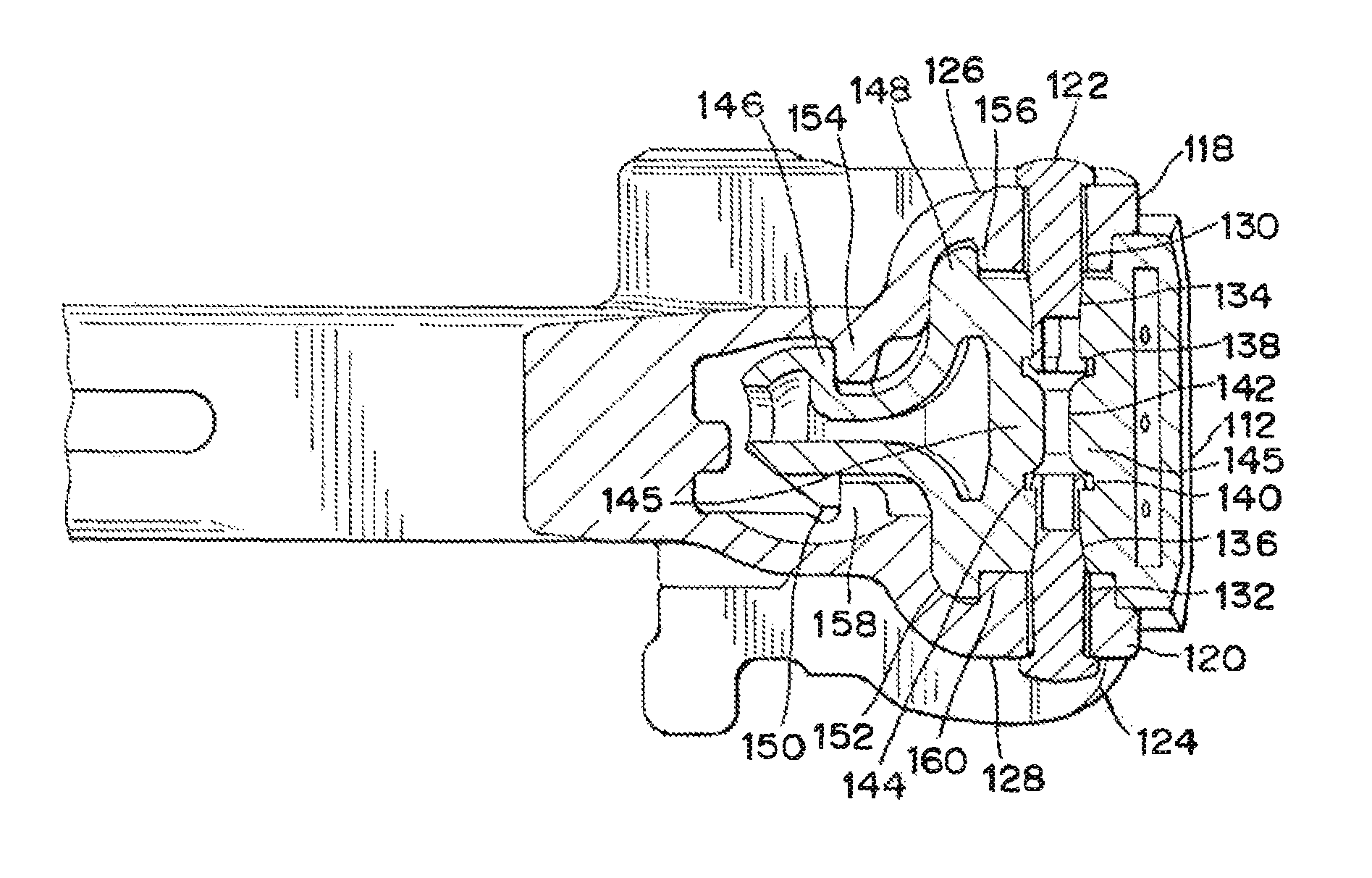
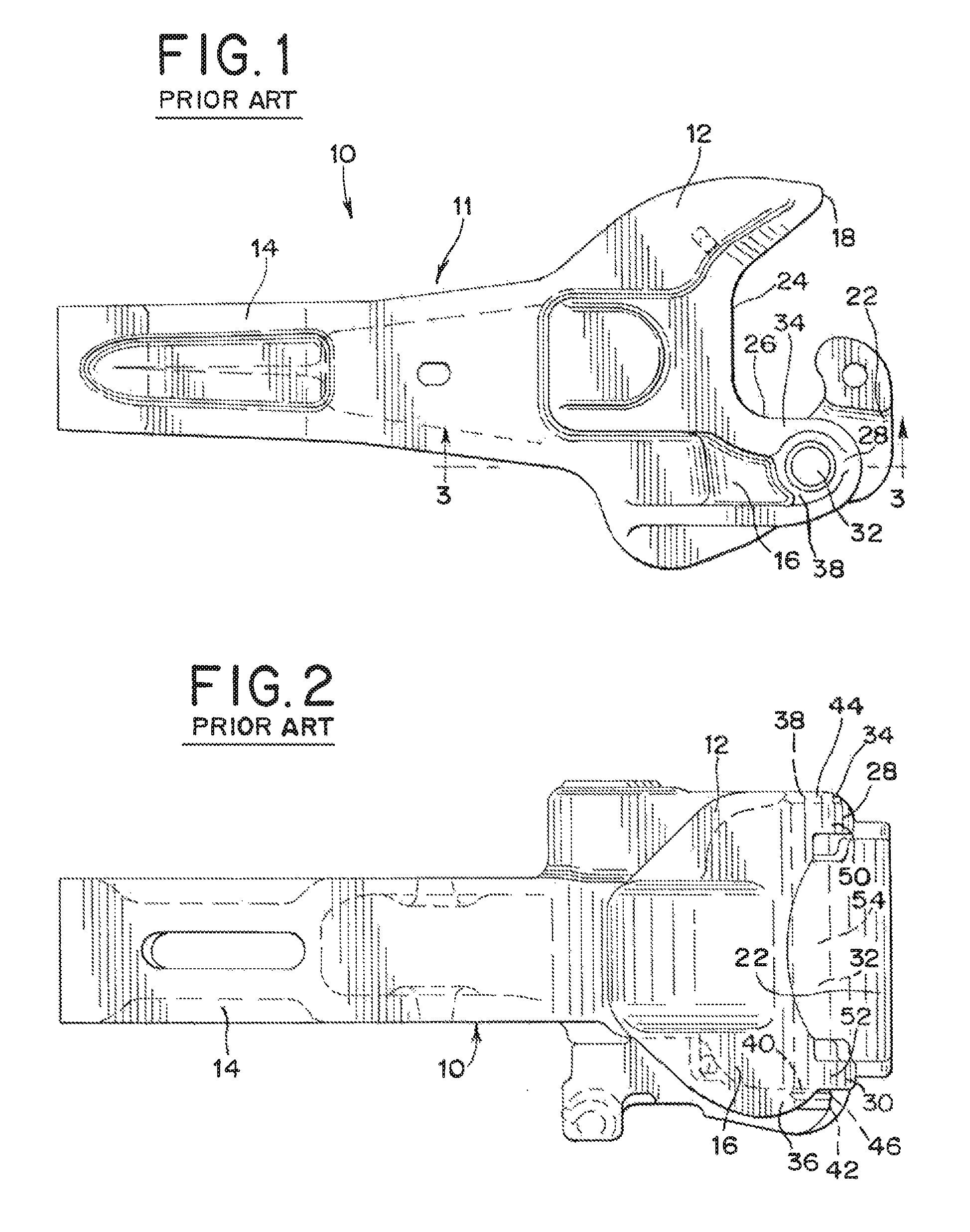
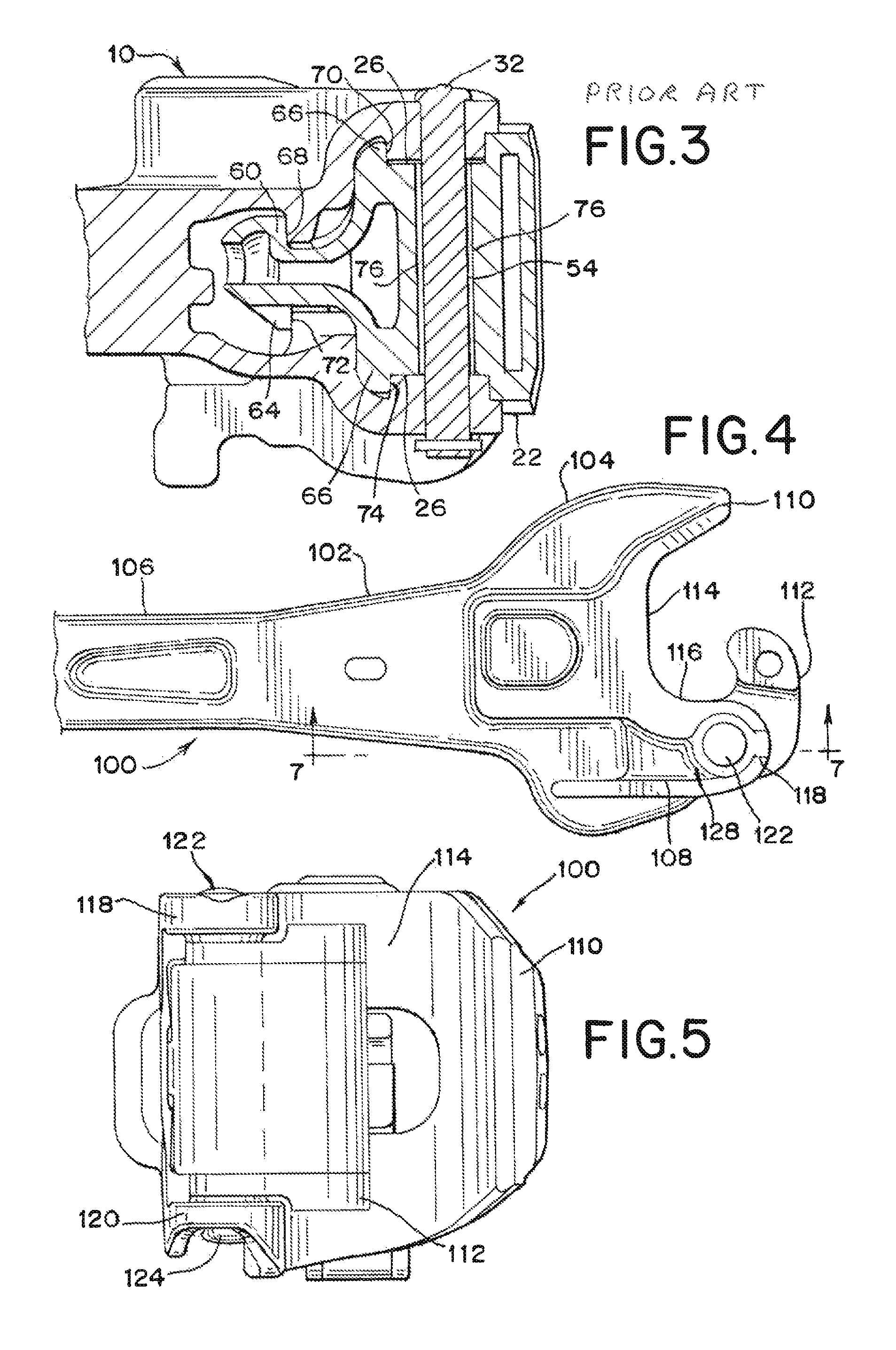
[0026]Referring now to FIGS. 1-3, an E-type coupler-knuckle assembly known in the prior art is generally designated 10 and includes a coupler body 11, a knuckle 22, and a knuckle pin 32. The coupler body 11 comprises generally a coupler head 12 and a coupler shank 14 which is adapted to be mounted on a railway car (not shown). The coupler-knuckle assembly 10 serves to transfer buff and draft loads that are exerted on the assembly 10 during use, from the knuckle 22 to the coupler body 11, without damaging knuckle pin 32.

[0027]The coupler head 12 has a knuckle side 16 and a guard arm side 18. Coupler head 12 has a front face 24 including a throat portion 26 extending towards the knuckle side 16 in a curved manner toward upper pivot lug 28 and lower pivot lug 30. Coupler head 12 includes outwardly protruding flange sections 34 and 36 from the top surface 38 of upper pivot lug 28 and the bottom surface 64 of lower pivot lug 30 respectively. Along with pulling and buffing loads on a coup...


PUM


Abstract

An improved coupler-knuckle assembly is comprised of a coupler body, a knuckle, and at least two knuckle retainer plugs. The knuckle has an internal coring geometry that increases the cross-sectional area of the throat portion of the knuckle compared to previous designs. The present invention's knuckle design includes a top and a bottom tapered holes in the knuckle with a locking groove at the bottom of each tapered hole for the knuckle retainer plugs to snap into. The knuckle retainer plugs are inserted through the coupler body and into the tapered holes in the knuckle. The improved coupler-knuckle assembly of the present invention reduces fatigue on the coupler, knuckle, and knuckle pin, prevents misalignment of the coupler-knuckle assembly, and prevents knuckle pin breakage.

Description

BACKGROUND OF THE INVENTION[0001]The invention relates generally to railway car coupling systems, and more particularly to an improved cast metal coupler-knuckle assembly.[0002]This invention is applicable to Association of American Railroads (AAR) Type E, F, and H couplers. In a standard railway coupler-knuckle assembly, a knuckle pin pivotally connects a coupler body and a knuckle. Both the coupler body and the knuckle have a pinhole that allows a single knuckle pin to pivotally secure the coupler and the knuckle together.[0003]In the coupler-knuckle assembly design that is currently used in the railway industry, the knuckle's weakest section is in the throat area around the hole for the knuckle pin. The hole is 1 21 / 32 inches in diameter and goes completely through the coupler and the knuckle. The pinhole reduces the cross-section area of the knuckle's throat area, which is a highly stressed location in the coupler-knuckle assembly. Because of this weakness in the throat area of ...

Claims


Application Information

Patent Timeline
Patent Type & Authority Patents(United States)
IPC IPC(8): B61G3/00
CPCB61G3/04B61G7/00
Inventor HALFORD, JOSEPHTODT, MATTHEWDUMEY, TIMOTHY
Owner AMSTED RAIL CO INC
Why Eureka
Try Eureka