
Connector

a technology of connecting rods and connectors, applied in the direction of coupling devices, two-part coupling devices, electrical equipment, etc., can solve the problems of erroneous signal transmission, easy cross-talk, and transmission of erroneous signals

Inactive Publication Date: 2014-12-16
DELTA ELECTRONICS INC
View PDF14 Cites 6 Cited by
  • Summary
  • Abstract
  • Description
  • Claims
  • Application Information

AI Technical Summary

Benefits of technology

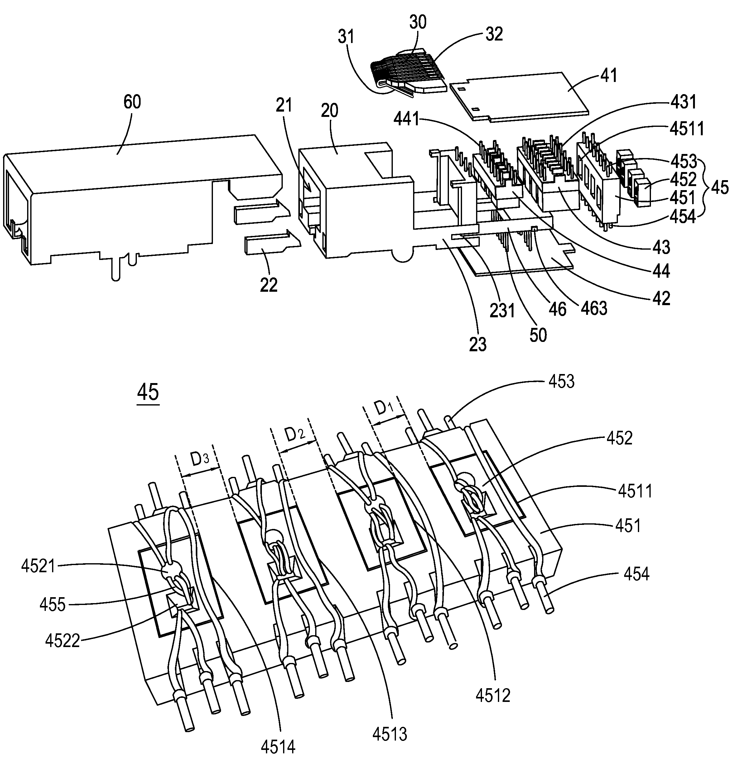
The present invention is a connector used for network communication that has a magnetic component to filter signals. It solves the issue of cross-talk caused by traditional connectors where the distance between signal channels is not fixed. By fixing the distance between magnetic cores, the distance between signal channels can be fixed, resulting in a more reliable and efficient connection.

Problems solved by technology

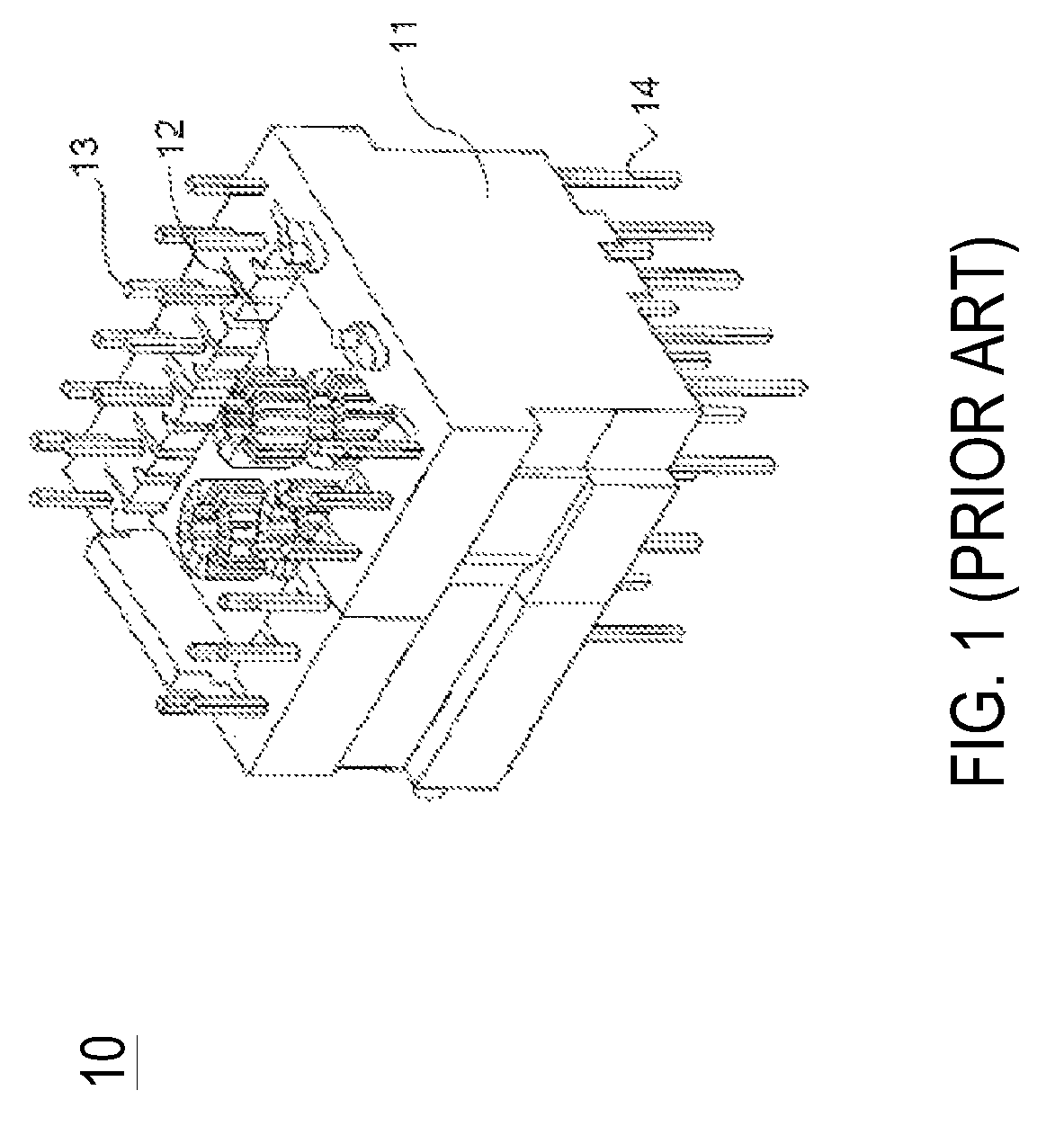
During the signal transmission process, the electromagnetic interference (EMI) is generated to cause the surrounding electronic components or circuits, resulting in erroneous signal transmission.
When the distance between any two magnetic cores 12 is too small, the cross-talk is easily caused between the signal channels, and even the erroneous signal transmission may be occurred.

Method used


Image

  • Connector
  • Connector
  • Connector

Examples


Embodiment Construction

[0013]The present invention will now be described more specifically with reference to the following embodiments. It is to be noted that the following descriptions of preferred embodiments of this invention are presented herein for purpose of illustration and description only. It is not intended to be exhaustive or to be limited to the precise form disclosed.

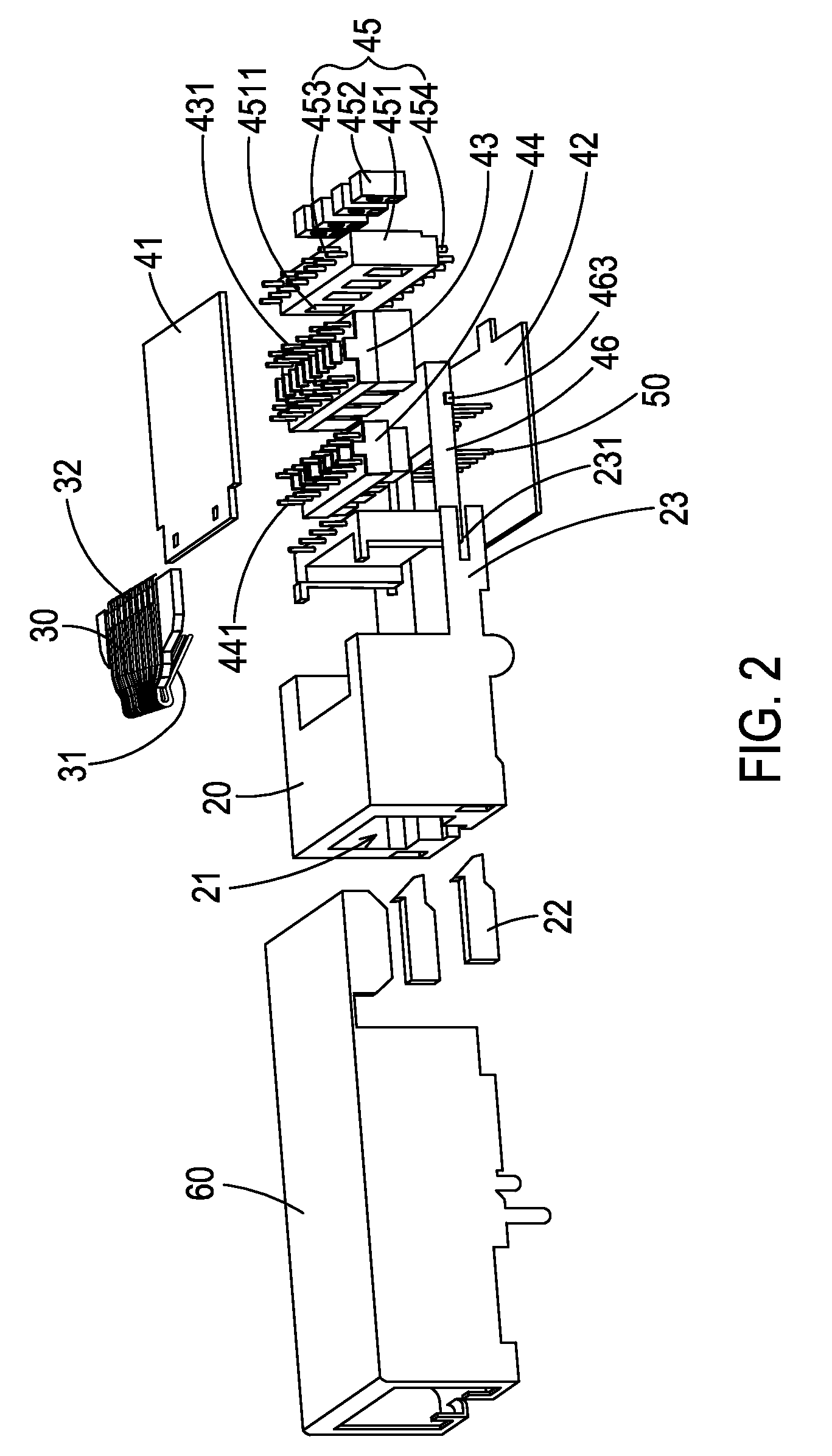
[0014]Please refer to FIGS. 2 and 3, which illustrate an exploded view and a cross-sectional view of the connector applied to the network communication according to a preferred embodiment of the present invention. The connector applied to network communication mainly includes a housing 20, a plurality of contact terminals 30, a signal processing module 40, a plurality of terminals 50 and a metal cover 60.

[0015]The connector is an RJ connector, such as the RJ45 connector shown in FIG. 2. However, the techniques of the present invention are not limited to the RJ45 connector, but also applied to other RJ connectors, such as RJ11, RJ...


PUM


Abstract

A connector comprises a housing, a plurality of contact terminals and a signal processing module. The housing has a receiving hole for receiving a plug. The plurality of contact terminals are disposed in the housing for being connected with the plug. The signal processing module is electrically connected with the contact terminals and has a first magnetic component, wherein the first magnetic component comprises a base and a plurality of magnetic cores, the base has a plurality of through holes, each of which has substantially the same size as that of the magnetic core so that the magnetic core is fixed in the through hole, and distances between adjacent two through holes are the same.

Description

FIELD OF THE INVENTION[0001]The present invention relates to a connector, and more particularly to a connector applied to network communication.BACKGROUND OF THE INVENTION[0002]With the development of the network communication techniques, the network connectors have been widely used in computers and various network equipments. RJ connectors are the most common network connectors, such as RJ11, RJ12 and RJ14 connectors using 4 pins or 6 pins for connection, and RJ45 connectors using 8 pins for connection, wherein RJ11 connectors are mainly used in telecommunication network and in charge of connections for telephone lines, and RJ45 connectors are mainly used in connections between network equipments for local area network (LAN) and asymmetric digital subscriber line (ADSL).[0003]When two network communication devices are connected through a connector plug and a socket, the network signals are able to be transmitted from the first device to the second device. During the signal transmis...

Claims


Application Information

Patent Timeline
Patent Type & Authority Patents(United States)
IPC IPC(8): H01R24/64H01R24/00H01R13/6461H01R13/66H01R13/719
CPCH01R13/719H01R24/64H01R13/6461H01R13/6633H01R23/025H01R24/00
Inventor KANG, YING-CHIANTAI, CHIN-CHUNGLIN, SHOU-CHENG
Owner DELTA ELECTRONICS INC
Learn More