Automotive fuse and relay block assembly

a technology for fuse and relay block, which is applied in the direction of relays, substation/switching arrangement casings, transportation and packaging, etc., to achieve the effect of increasing the footprint and reducing accessibility

Inactive Publication Date: 2014-12-16
SUMITOMO WIRING SYST LTD
View PDF6 Cites 12 Cited by
  • Summary
  • Abstract
  • Description
  • Claims
  • Application Information

AI Technical Summary

Benefits of technology

[0018]The fuse and relay block module assembly preferably further comprises front and rear covers that are mounted around the circuit board and the fuse connectors and / or relay connectors of the relay block module assembly. The front and rear covers of the relay block module assembly are configured to be locked releasably together and may enclose certain of the fuses and / or relays therein. However, parts of the front or rear covers may include openings so that certain fuses and / or relays can be mounted in the respective connectors without separating the front and rear covers. The openings in the front or rear covers preferably are at upper parts of the relay block module assembly and above the relay block and the relay block collar for easy access.
[0019]The fuse and relay block assembly is mounted in the vehicle with the relays and fuses protectively enclosed between the upper and lower covers. All of the relays and fuses mounted on the relay block can be accessed for replacement merely by removing the upper cover. Relays and fuses in the relay block can be removed parallel to the mounting direction. Fuses and / or relays at least in the upper part relay block module assembly can be removed in the transverse direction that is perpendicular to the mounting direction of the fuses and relays of the relay block. The above-described relay block module enables a significant increase in the number of fuses and relays that can be accommodated in the fuse and relay block assembly without increasing the footprint and without reducing accessibility.

Problems solved by technology

However, the space available in a vehicle is at a premium and the fuse and relay block must compete with other necessary parts of the vehicle for the limited space.
The teaching of JP 2003-079027 leads to manufacturing and design efficiencies, but does not address the problems caused by an increased number of electrically powered components in the vehicle and the corresponding need to accommodate a larger number of easily accessible fuses and relays in a limited available space.

Method used


Image

  • Automotive fuse and relay block assembly
  • Automotive fuse and relay block assembly
  • Automotive fuse and relay block assembly

Examples


Embodiment Construction

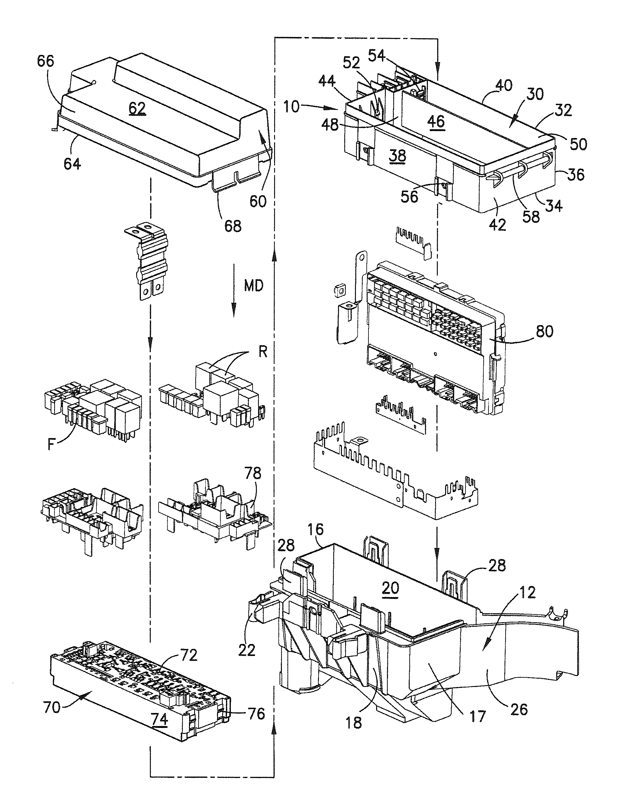
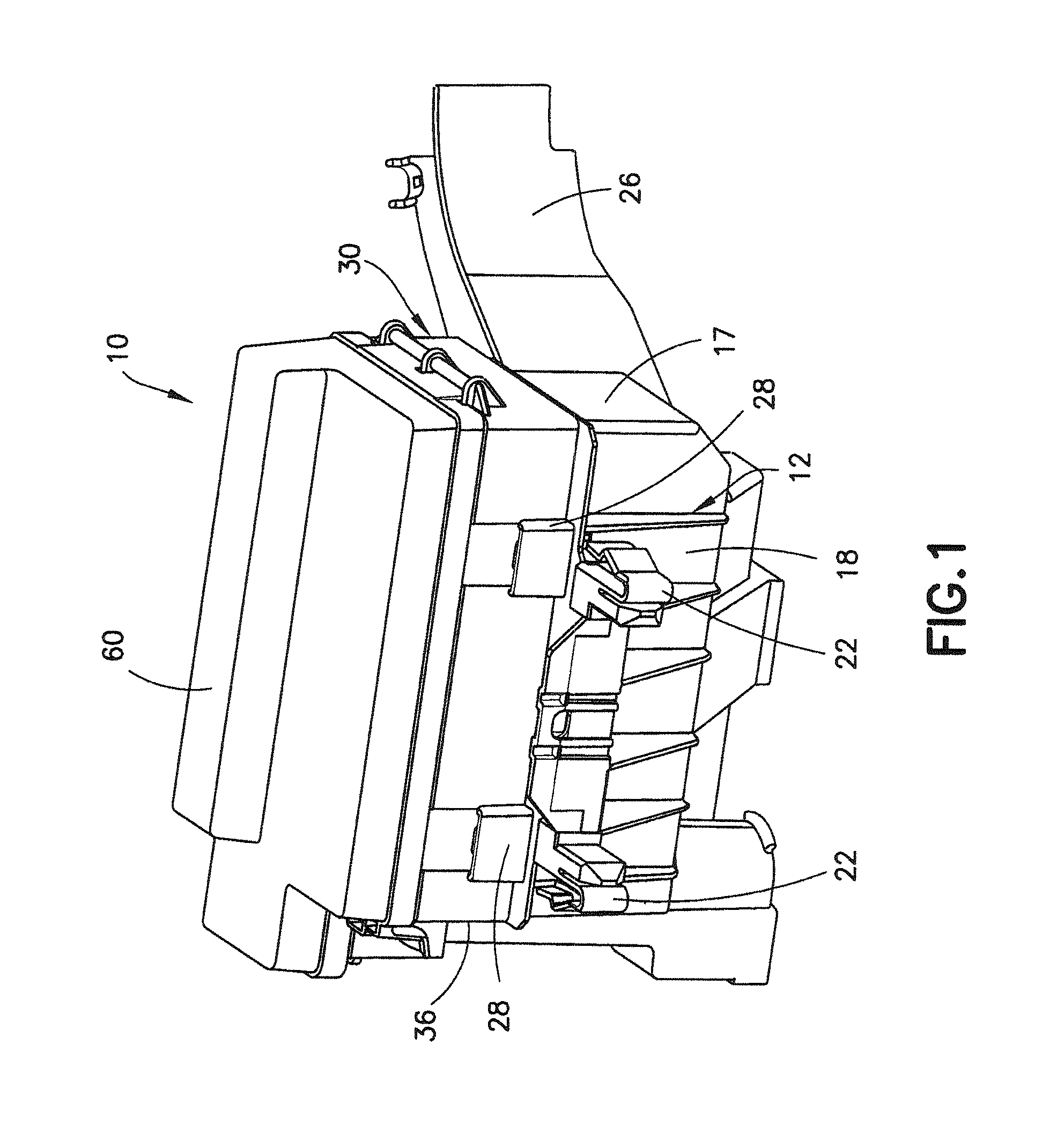
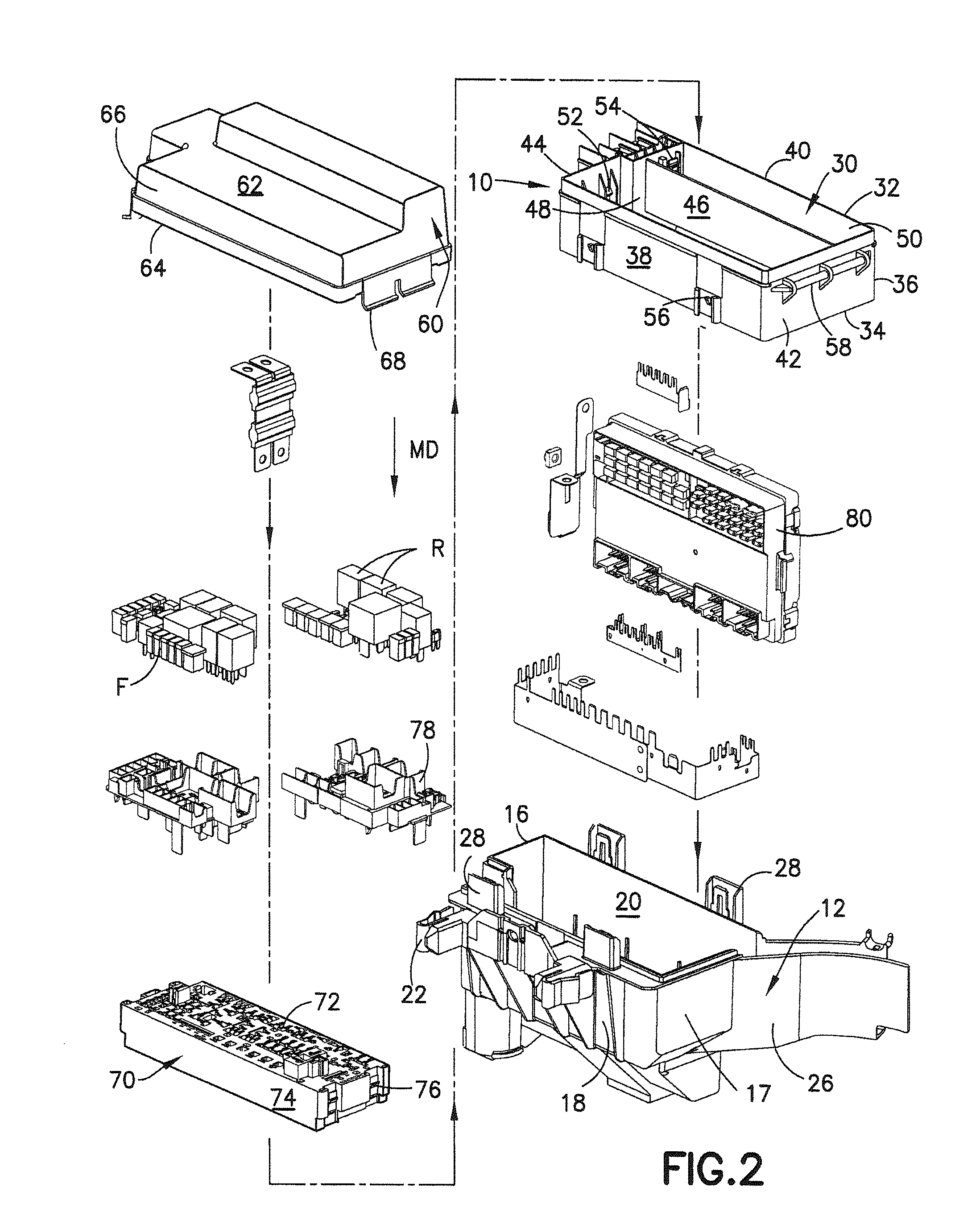
[0028]A fuse and relay block assembly in accordance with the subject invention is identified generally by the numeral 10 in FIGS. 1 and 2. The fuse and relay block assembly 10 includes a lower cover 12 with a closed bottom 14, an open top 16 and a sidewall enclosure 17 extending between the bottom 14 and the top 16. The sidewall enclosure 17 includes opposite front and rear walls 18 and 20. Mounting projections 22 extend out from the front wall 18. Each mounting projection 22 is dimensioned and configured to be inserted into a mounting aperture in a panel of an automotive vehicle and includes a resiliently deflectable locking finger 24 that can lock with a surface of the panel adjacent the mounting aperture to hold the lower cover 12 in position on the panel. A wiring harness guide 26 projects diagonally out from a corner of the sidewall enclosure 17 adjacent the rear wall 20 and communicates with the area enclosed by the sidewall enclosure 18. The wire harness guide 26 is dimension...


PUM


Abstract

A fuse and relay block assembly (10) for an automotive vehicle includes a lower cover (12) and an upper cover (60) mounted in substantially opposed relationship to one another. A relay block (70) is mounted between the lower cover (12) and the upper cover (60) and can receive electrical devices (R, F) mounted along a mounting direction (MD). A relay module assembly (80) is mounted between the lower cover (12) and the upper cover (60) and can receive electrical devices (R, F) mounted along a transverse direction (TD) substantially perpendicular to the mounting direction (MD). Thus, a greater density of electrical devices (R, F) can be mounted within a smaller footprint.

Description

BACKGROUND OF THE INVENTION[0001]1. Field of the Invention[0002]The invention relates to a fuse and relay block assembly for an automotive vehicle.[0003]2. Description of the Related Art[0004]A fuse and relay block for an automotive vehicle includes a housing, a relay / fuse module mounted in the housing and a cover removably mounted to the housing for covering and protecting the relay / fuse module. Relay connectors and fuse connectors are mounted on the relay / fuse module and are connected by wires to electrically powered components of the vehicle, such as the windshield wipers, the fuel pump, the water pump, cooling fans, an air conditioner compressor, power windows, power doors, door locks, power seats, the sound system, the navigation system and various lighting groups, the horn. Relays and fuses are mounted removably in the relay and fuse connectors of the relay / fuse module.[0005]Fuses protect certain of the electrically powered components of the vehicle from damage due to a curren...

Claims


Application Information

Patent Timeline
Patent Type & Authority Patents(United States)
IPC IPC(8): H02B1/26
CPCH02G3/086B60R16/0238H01H2085/208H01H50/021H01H2050/049
Inventor DEPP, CHARLESMATSUMURA, AKIHIRO MAXCARNICK, BRIANZUKOWSKI, NATHAN
Owner SUMITOMO WIRING SYST LTD
Why Eureka
Try Eureka