Physical vapor deposition apparatus having a tapered chamber

Active Publication Date: 2018-03-20
STABILE JAMES
View PDF48 Cites 7 Cited by
  • Summary
  • Abstract
  • Description
  • Claims
  • Application Information

AI Technical Summary

Benefits of technology

[0009]Accordingly, it is therefore an object of this invention to provide a physical vapor deposition (PVD) apparatus having a Tapered L

Problems solved by technology

Conventional physical vapor deposition (PVD) systems generally have chambers that include a cylindrical, rectangular, bell or D-shaped chamber as illustrated in FIGS. 1A, 1B, 1C and 1D, and they are typically large and costly.
A dead space of less than eighteen inches can adversely affect the uniformity of the coating material because the outp

Method used


Image

  • Physical vapor deposition apparatus having a tapered chamber
  • Physical vapor deposition apparatus having a tapered chamber
  • Physical vapor deposition apparatus having a tapered chamber

Examples


Embodiment Construction

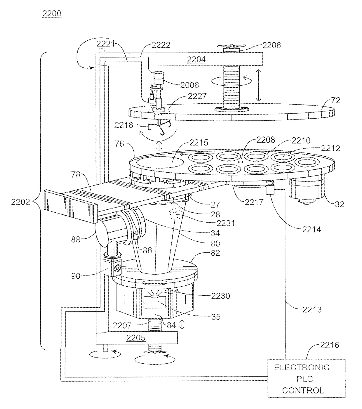
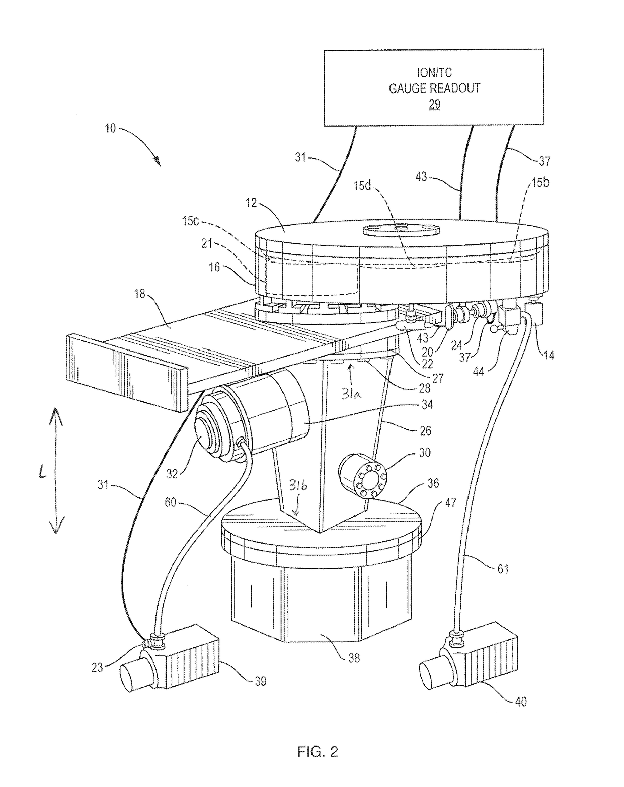
[0050]FIG. 2 is a front perspective view of an exemplary embodiment of a physical vapor deposition apparatus 10. FIG. 3 is a cross-sectional view of the physical vapor deposition apparatus 10 of FIG. 2, omitting a high vacuum pump for clarity. FIG. 19A depicts a downward view of an apparatus similar to the apparatus 10. FIG. 20A depicts a side view of an apparatus similar to the apparatus 10.

[0051]Referring to FIGS. 2 and 3, the physical vapor deposition (PVD) apparatus 10 can be used, for example, to coat silicon wafers, solar cells, and / or any other suitable parts that receive coatings. In exemplary embodiments, the (PVD) apparatus 10 can be operable to deposit ultra-thin and ultra-uniform coatings having dimensions that are typically measured in nanometers, angstroms or microns. In some embodiments, the PVD apparatus 10 can be used with thermal evaporation sources, sputtering sources, ion mill sources, etching electrodes, and / or any other high vacuum process that would generally ...


PUM

PropertyMeasurementUnit
Volumeaaaaaaaaaa
Areaaaaaaaaaaa
Vacuumaaaaaaaaaa

Abstract

A physical vapor deposition (PVD) apparatus having a deposition chamber and a source chamber of minimal volume, which can be selectively isolated from each other by a various load-lock valves. Exemplary embodiments can include a tapered high vacuum chamber disposed between the deposition chamber and the source chamber. The pump down time of the apparatus can be reduced, as compared to conventional PVD systems, due to the combined reduced volume of the chambers. Coating uniformity can also be improved by spinning each part to be coated on its' own axis while selectively exposing to a deposition source with minimal particle generation.

Description

CROSS REFERENCE TO RELATED APPLICATIONS[0001]This application is a continuation-in-part of U.S. patent application Ser. No. 13 / 241,777, filed Sep. 23, 2011, which claims priority to Provisional Application No. 61 / 386,617, filed Sep. 27, 2010, each application of which is incorporated herein by reference in its entirety.FIELD OF THE INVENTION[0002]Certain of the embodiments relate generally to a physical vapor deposition apparatus, and more particularly, to a physical vapor deposition apparatus having a Tapered Load-locked Chamber (TLC).DESCRIPTION OF RELATED ART[0003]Conventional physical vapor deposition (PVD) systems generally have chambers that include a cylindrical, rectangular, bell or D-shaped chamber as illustrated in FIGS. 1A, 1B, 1C and 1D, and they are typically large and costly. A space between an evaporation source, such as an electron beam gun, disposed at a bottom of the chamber, and parts to be coated, such as a semiconductor wafer, disposed towards the upper portion ...

Claims


Application Information

Patent Timeline
IPC IPC(8): C23C16/00C23C14/22
CPCC23C14/22C23C14/505C23C14/566
Inventor STABILE, JAMES
Owner STABILE JAMES
Why Eureka
Try Eureka