Visual warning device for weight bearing

a warning device and weight bearing technology, applied in the field of visual warning devices for weight bearings, can solve the problems of device failure to alarm, potential injury, and eminent risk of further injury

Active Publication Date: 2014-12-23
PHYSICAL THERAPY SERVICES
View PDF27 Cites 4 Cited by
  • Summary
  • Abstract
  • Description
  • Claims
  • Application Information

AI Technical Summary

Problems solved by technology

There is no indication Yaglou, skilled in the art, ever intended this device be used for observing urge applied through weight bearing of a lower limb because it was unobvious to the inventor.
If the source of energy fails, there is no indication of excessive urge being applied and the risk of further injury is eminent.
At no time did Gradisar, although skilled in the art, anticipate using the device claimed for visually monitoring weight bearing with a gauge or Liquid-crystal Diode (herein referred to as LCD) located on an assistive walking device because it was unobvious to the inventor.
In the event of energy failure, the device would fail to alarm without the user recognizing the malfunction.
Failure of the alarm would cause risk of excessive urge on the extremity causing potential injury.
It is possible this device may leak from the fluid cell causing a slipping hazard and risk of injury.
This is a critical issue.
At no time did Pfeiffer, skilled in the art, anticipate the use of a gauge or LCD or the placement of the gauge or LCD within view of the user or caregiver because it was unobvious to this inventor.
Failure in the adjusting component may cause the wrong designated urge to be monitored.
Reviewing the concerns one must recognize the possibility of fluid leaking, failure of the energy source and the user having a hearing deficit as well as failure to adjust the level of urge monitored. Mr. Sipe's claims, skilled in the art, did not anticipate using a gauge or LCD attached to an assistive walking device for visual monitoring because it was unobvious to this inventor.
U.S. Pat. No. 4,648,918 to Goforth (1987) teaches monitoring over a period of time weight bearing by multi-event notification regarding conditions such as diabetes and, after review, is not considered because it does not allow for monitoring during ambultion.
Although skilled in the art, it was unobvious and not in the inventor's interest to attach an LCD or gauge to an assistive walking device to visually monitor weight bearing when limited weight bearing has been prescribed.
Due to the complication of the circuitry, any component may fail without the user recognizing the hazard of excessive urge.
Again we can suspect fluid leakage, source of energy failure, loss of hearing and co-morbidities causing loss of sensation in the lower extremity, such as Diabetes Mellitus.
Although skilled in the art, the concept of placing an LCD or gauge on an assistive walking device for visual monitoring was unobvious to Knotts et al.
However, the display is not deliberately placed in a position where the user or observer can see his or her own amount of weight bearing.
In spite of the fact that the inventor was skilled in the art, it was unobvious to Thomas et al. to monitor the force described with an LCD or gauge attached to an assistive walking device.
Although, skilled in the art, inventor Gray was unobvious of the concept of employing an LCD or gauge to visually monitor force applied to an assistive walking device.
U.S. Pat. No. 5,285,022 to Antone (1994) teaches “A partial weight-bearing scale including a planer weighing surface and a fixed load supporting platform to one side of the weighing surface.” This is not considered because it is not attached to the lower limb and is not capable of being mobilized with the user.

Method used


Image

  • Visual warning device for weight bearing
  • Visual warning device for weight bearing
  • Visual warning device for weight bearing

Examples


embodiment

Preferred Embodiment

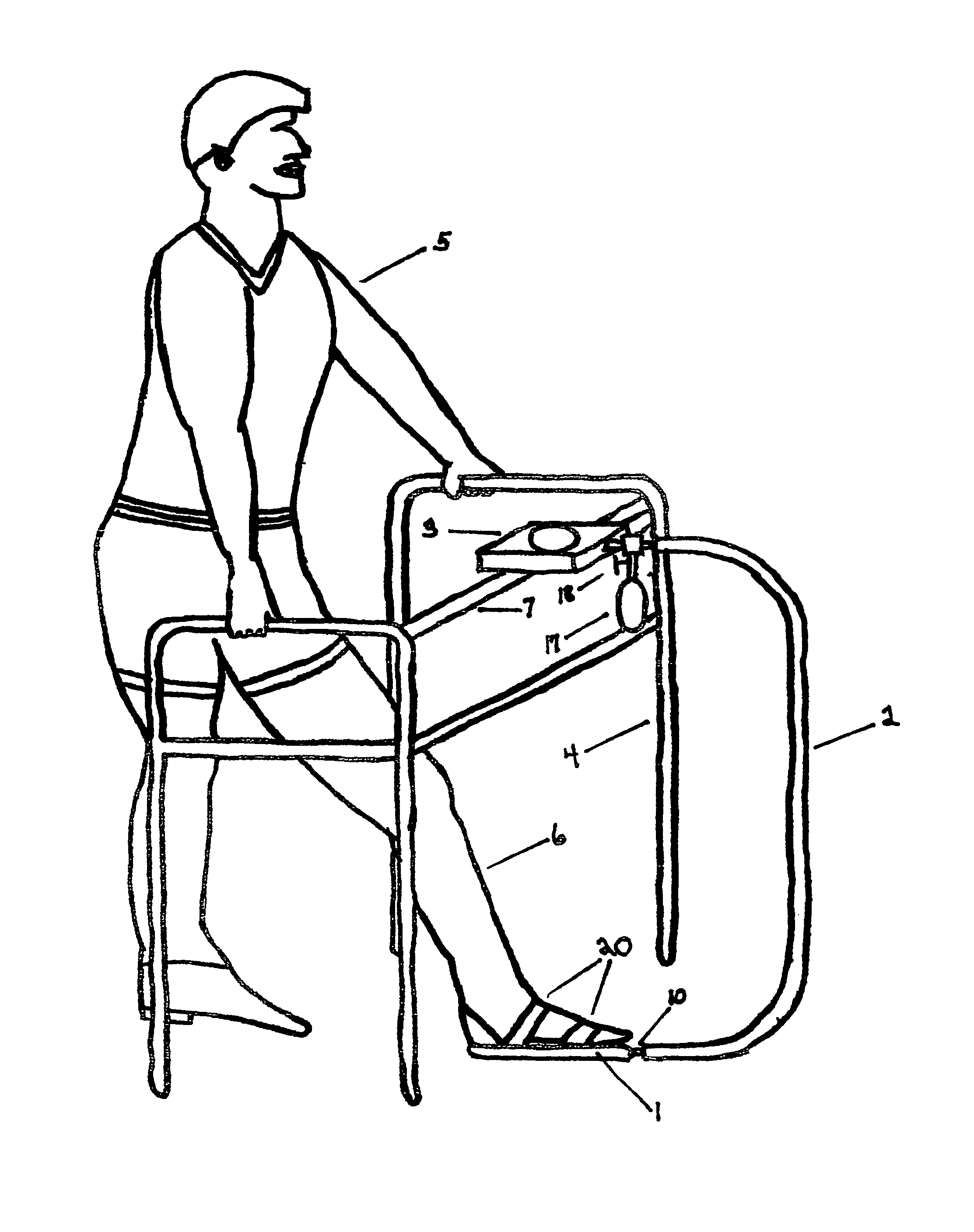
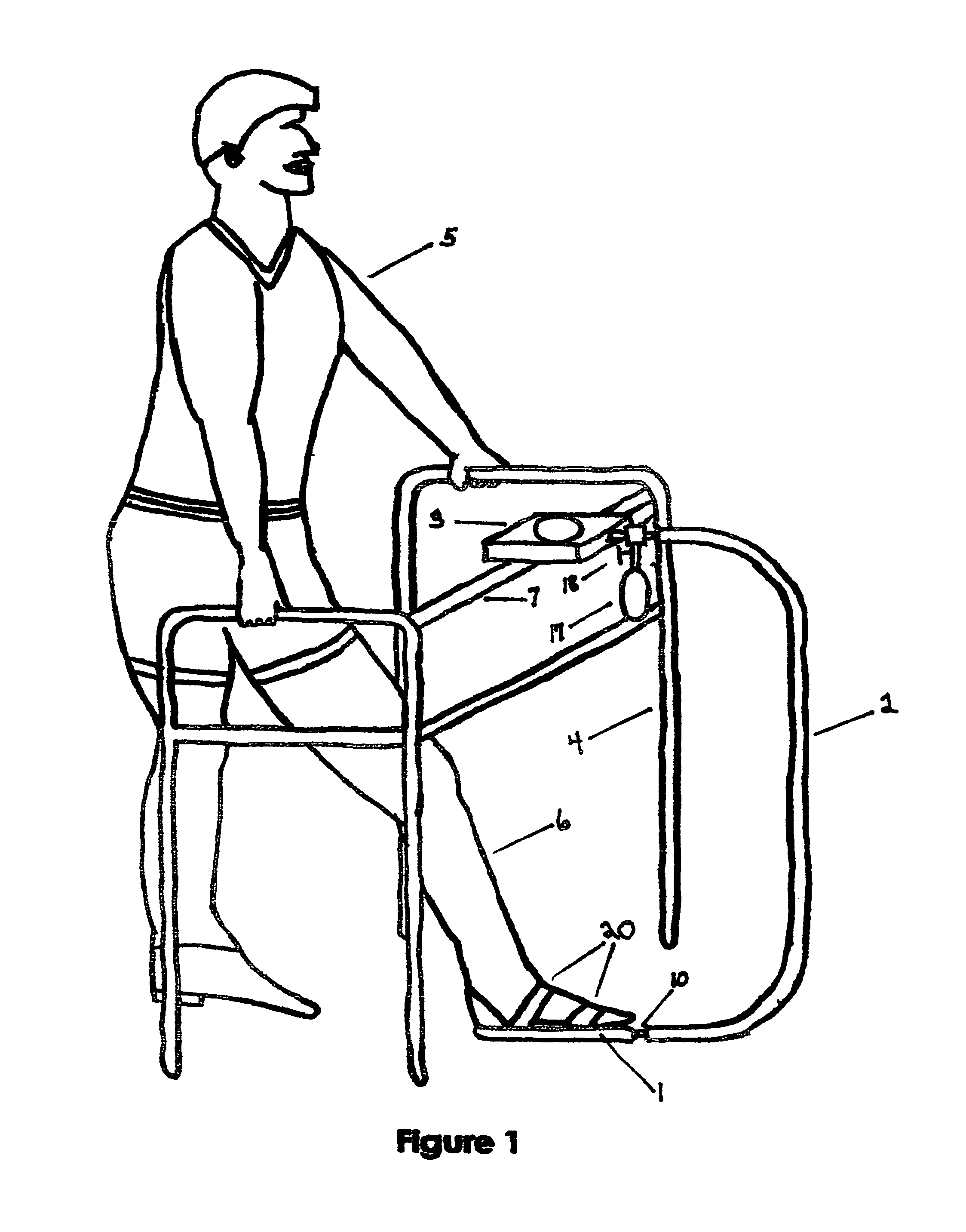
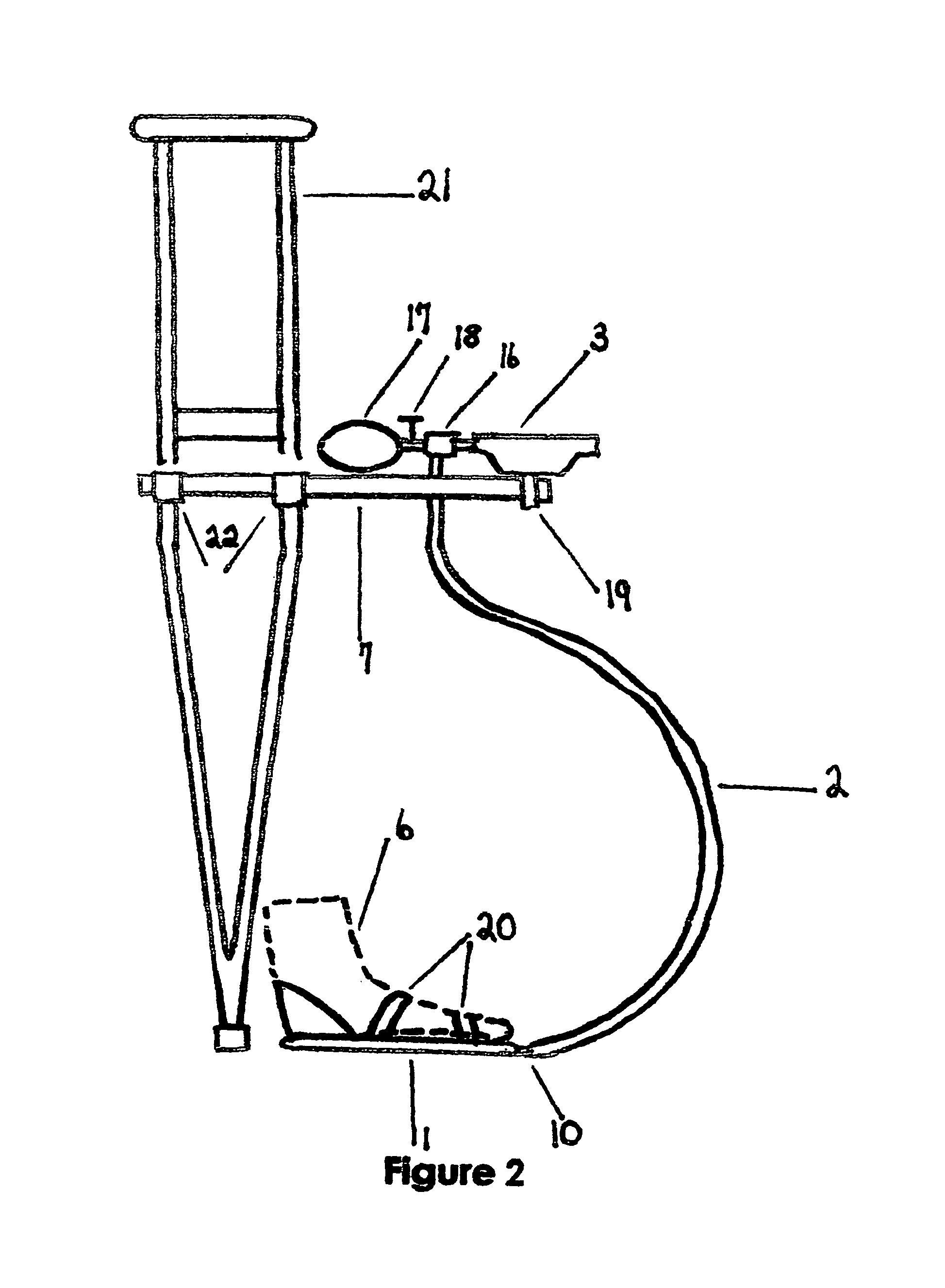
[0085]The first embodiment of the device is illustrated in FIG. 1 with further detailing in FIGS. 2 and 3. FIG. 1 represents user (5), standing with walker (4), wearing foot appendage component containing bladder (1). This is fastened by straps (20) to the foot of user's lower extremity requiring limited weight bearing (6). By stepping on said bladder (1) urge is transmitted via tube or hose (2) fastened to bladder (1) by nozzle (10) extending upward to three way connector (16) seen in FIG. 2. Opposing end of said connector (16) attaches to nozzle of said gauge (3). Said user (5) can visualize said gauge (3) attached to horizontal bar (7) of said walker (4) by bracket (19). Said user (5) or caregiver can easily observe urge applied by said foot (6) requiring limited weight bearing. Squeeze bulb (17) attached to said connector (16) forces air into bladder (1) to establish a zero point of pressure with indicator needle (14) noted in FIG. 3. Valve (18) seen in FIG. ...


PUM

PropertyMeasurementUnit
weightaaaaaaaaaa
weightaaaaaaaaaa
weightaaaaaaaaaa

Abstract

An improved weigh bearing monitor determining weight or urge applied upon an impaired lower extremity when limited weight bearing is prescribed by a medical professional. The limited amount of weight borne on the affected limb visualized on gauge (3) attached to assistive walking device (4) with weight borne readable on gauge (3) located within visual range of the user or caregiver. The device consists of gauge (3) connected to assistive walking device (4) connected by hose or tube (2) to foot appendage component containing bladder (1) attached to user's (6) foot. When user (5) applies pressure upon bladder (1), then gauge (3) is in view of user (5) or caregiver monitoring weight applied to the affected limb. This device may also be wireless with elimination of the hose. This device may also be hydraulic or pneumatic in accordance with variation maintaining the visual ability of user or caregiver.

Description

CROSS REFERENCE TO RELATED APPLICATIONS[0001]Not ApplicableFEDERALLY SPONSORED RESEARCH[0002]Not Applicable[0003]1. Field[0004]This application relates to a device providing the ability to visually monitor the amount of weight being placed on a user's foot when a medical professional prescribes weight bearing limits.[0005]2. Present Methods for Control of Weight Bearing[0006]The human being is bipedal. When establishing a gait pattern, weight is shifted with the entire weight of the body applied to one extremity, called the stance phase of walking, while the other extremity moves through a swing phase. When the swing phase is concluded, the swinging lower extremity begins weight bearing, generally referred to as the stance phase, while the opposing lower extremity moves through a swing phase.[0007]Often, after injury, orthopedic surgery, ulceration or other lesion of the foot, a physician may require the patient to limit the amount of weight placed on one foot, with the limitation f...

Claims


Application Information

Patent Timeline
Patent Type & Authority Patents(United States)
IPC IPC(8): A61B5/103G01L7/00A61B5/00
CPCA61B5/103A61B2505/09A61B2562/0252A61H3/00A61H2201/0184A61H2201/164A61H2201/5071A61H2230/805
Inventor WARD, FREDERICK, ALBERT
Owner PHYSICAL THERAPY SERVICES
Why Eureka
Try Eureka