Inductively-heated applicator system

a technology of applicators and heating elements, which is applied in the field of inductive heating of applicators, can solve the problems of more complex applications, and achieve the effects of reducing the heating of products in the applicator, reducing the heating of products, and improving the response to products

Inactive Publication Date: 2014-12-30
ACCESS BUSINESS GRP INT LLC
View PDF92 Cites 15 Cited by
  • Summary
  • Abstract
  • Description
  • Claims
  • Application Information

AI Technical Summary

Benefits of technology

[0007]In one embodiment, the applicator includes a roller element for applying a serum, salve or other health and beauty products. The roller element may be manufactured from a material that heats in the presence of electromagnetic waves. In an alternative embodiment, a portion of the applicator tip is manufactured from a material that heats in the presence of electromagnetic waves. In another alternative embodiment, the roller element is partially enclosed in an isolator to thermally isolate and remove the roller element from the flow path of the product. A retainer may also assist in directing the flow path of the product.
[0011]The present invention provides an inductively-heated applicator system that permits application of heated serums, salves and other health and beauty products to localized areas of a person's body. The system includes an applicator that is heated without wires or other direct electrical connections. Among other things, this simplifies use and operation of the applicator. Some products degrade faster once they have been heated. In some embodiments, heating of the product in the applicator is minimized in favor of heating either the product once it is external to the applicator or heating the area of interest to prepare the area to better respond to the product. Heat may also increase the rate at which some products are absorbed into the body and provide a warm sensation that can be more appealing than an experience with a room temperature applicator.

Problems solved by technology

In some applications, the applicator may be more complex and may include a reservoir for the product.

Method used


Image

  • Inductively-heated applicator system
  • Inductively-heated applicator system
  • Inductively-heated applicator system

Examples


Embodiment Construction

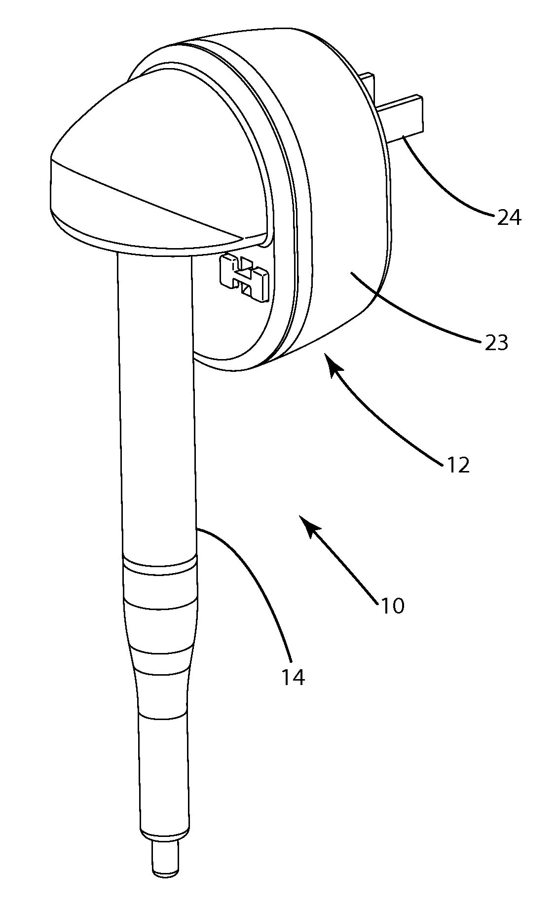
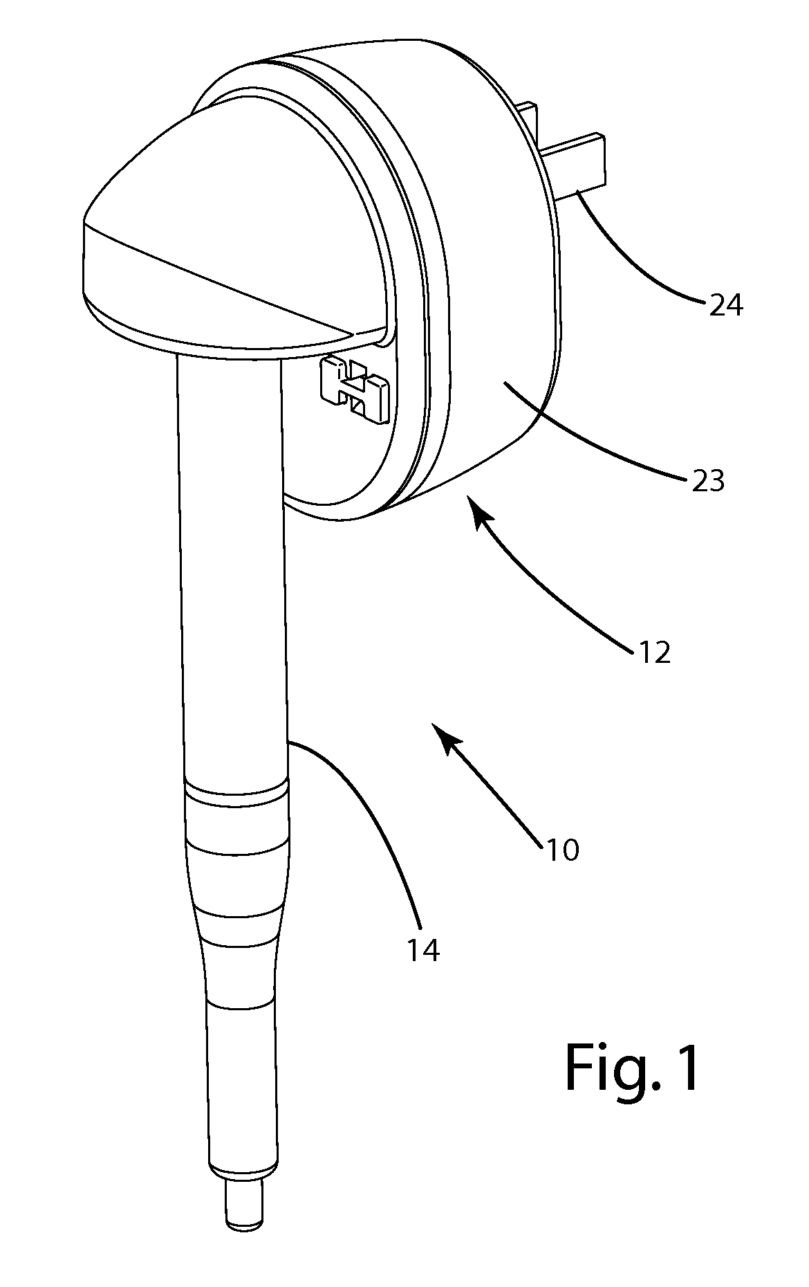
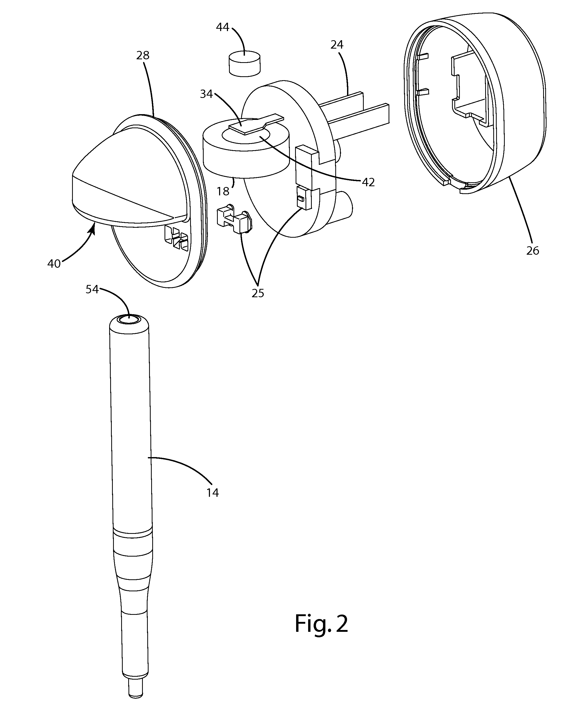
[0027]An inductively-heated applicator system in accordance with an embodiment of the present invention is shown in FIGS. 1-3. The applicator system 10 generally includes a heating module 12 and an applicator 14. The heating module 12 includes circuitry 16 for generating a varying electromagnetic field. The circuitry 16 may include a primary 18 for generating the electromagnetic field. The heating module 12 may also include a dock 43 for removably retaining the applicator 14 in the presence of the electromagnetic field. The heating module 12 may include a magnet 44, or other retaining mechanism to assist in retaining the applicator 14. The applicator 14 includes a dispensing system, an applicator system and a heating element 22. The heating element 22 may be independent or part of the dispensing or applicator system. In the illustrated embodiment, the heating element 22 is a roller element that is inductively heated when positioned within the electromagnetic field. In an alternative...


PUM


Abstract

An inductively-heated applicator system including a heating module and applicator or applicator pen. The heating module includes a dock for seating the applicator. The heating module includes circuitry to selectively generate an electromagnetic field to wirelessly provide energy to the applicator when it is positioned in the dock. The heating module may also include temperature control circuitry to at least one of monitor and control the temperature of the applicator. The applicator pen includes a heating element that may be heated through energy provided by the electromagnetic field. The heating element may be directly inductively heated by the electromagnetic field. The heating element may be a roller element that heats and applies the product. Alternatively, the applicator may include a secondary in which electrical power is induced when the electromagnetic field is present. In this alternative, the power may be applied to the heating element to produce resistive heat.

Description

BACKGROUND OF THE INVENTION[0001]The present invention relates to applicators for health and beauty products, and more particularly to applicators for applying health and beauty products in a heated state.[0002]A wide variety of serums, salves and other health and beauty products are available for topical application. In some applications, these products are applied simply by hand. With many products, however, an applicator is available to assist the user in applying the product.[0003]Applicators are available in a variety of different types. Simple applicators may utilize a brush or foam pad to apply the product. In some applications, the applicator may be more complex and may include a reservoir for the product. One conventional applicator includes a rolling ball for applying the product. In a typical rolling ball applicator, the rolling ball is positioned in the neck of a product reservoir with a portion exposed on the exterior of the applicator. As the rolling ball is rolled wit...

Claims


Application Information

Patent Timeline
Patent Type & Authority Patents(United States)
IPC IPC(8): B05C1/00H05B6/10H05B6/04H02J7/00A45D40/26B05C17/00
CPCH05B6/105B05C1/00B05C1/003A45D2200/055A45D2200/056A45D40/261A45D2200/155H02J7/025A45D34/041B05C17/001
Inventor BAARMAN, DAVID W.BYLSMA, RICHARDLEPPIEN, THOMAS JAYLEVERETT, JESSE C.MORK, STEVE O.
Owner ACCESS BUSINESS GRP INT LLC
Why Eureka
Try Eureka