Optical image lens assembly, image capturing apparatus and electronic device

a technology of optical image lens and image capturing apparatus, which is applied in the direction of optics, optical elements, instruments, etc., can solve the problems of unfavorable reducing the number of optical elements used in the optical system, color distortion of the image, and thickness of the ir-cut filter

Active Publication Date: 2018-03-08
LARGAN PRECISION
View PDF7 Cites 12 Cited by
  • Summary
  • Abstract
  • Description
  • Claims
  • Application Information

AI Technical Summary

Benefits of technology

[0049]In the optical image lens assembly according to the present disclosure, when the average transmittance in the wavelength range of 400 nm-650 nm of the optical lens element including the long-wavelength light absorbing agent is T4065, the following condition can be satisfied: 75%≦T4065. Therefore, an excellent respond of the image sensor for the visible lights can be maintained which is favorable for maintaining the color authenticity so as to reduce the degree of color shift.

Problems solved by technology

However, the image sensor not only receives and responds to visible lights but also responds to infrared lights which is invisible for human eyes.
If the infrared lights are not filtered when photographing, the color of the image will be distorted.
However, the IR-cut filter has a certain thickness, which is unfavorable for reducing the volume of the optical system and is unfavorable for reducing the number of optical elements used in the optical system.
Accordingly, the optical system is unfavorable to be applied to compact mobile products.
However, the blue glass filters filter the infrared lights by absorbing the infrared lights, which requires a sufficient thickness for effectively absorbing the infrared lights.
Accordingly, the back focal length of the optical system is increased, which is unfavorable for maintaining the compact size of the optical system.
However, the volume of the optical system cannot be reduced easily due to the large number of lens elements.
Also, with the large number of lens elements, the optical system has the drawback of protruding from the surface of the mobile product, which is unfavorable for featuring the mobile product with a thin thickness and an aesthetic design, thereby the importance of reducing the number of the optical elements used in the optical system is highlighted.

Method used


Image

  • Optical image lens assembly, image capturing apparatus and electronic device
  • Optical image lens assembly, image capturing apparatus and electronic device
  • Optical image lens assembly, image capturing apparatus and electronic device

Examples


1st embodiment

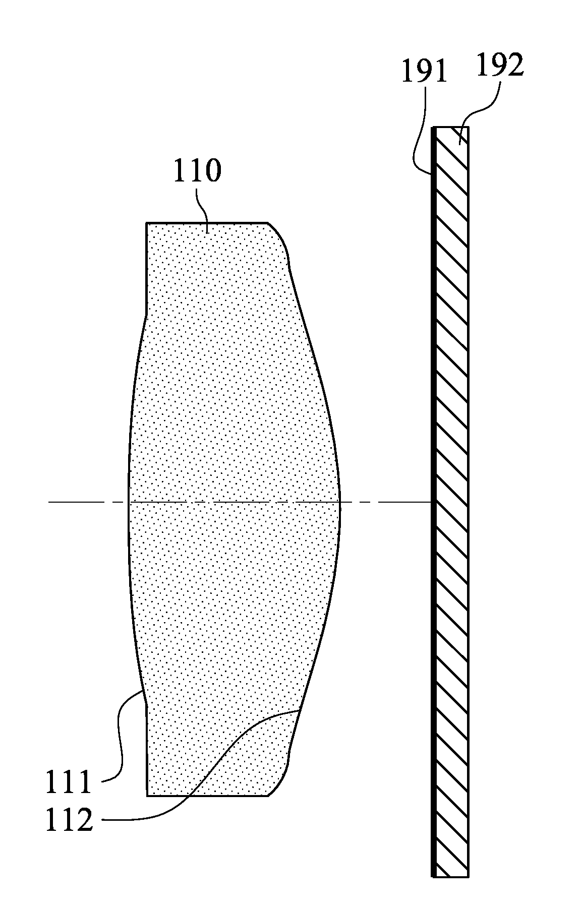
[0077]FIG. 1 is a schematic view of an image capturing apparatus according to the 1st embodiment of the present disclosure. In FIG. 1, the image capturing apparatus includes an optical image lens assembly (its reference numeral is omitted) and an image sensor 192. The optical image lens assembly includes, in order from an object side to an image side, a first optical lens element 110 and an image surface 191, wherein the image sensor 192 is disposed on the image surface 191 of the optical image lens assembly. The optical image lens assembly can selectively include other elements, such as an aperture stop (not shown). The other elements are not the key points and will not be described herein.

[0078]The first optical lens element 110 with positive refractive power has an object-side surface 111 being convex in a paraxial region thereof and an image-side surface 112 being convex in a paraxial region thereof, and has the object-side surface 111 and the image-side surface 112 being both a...

2nd embodiment

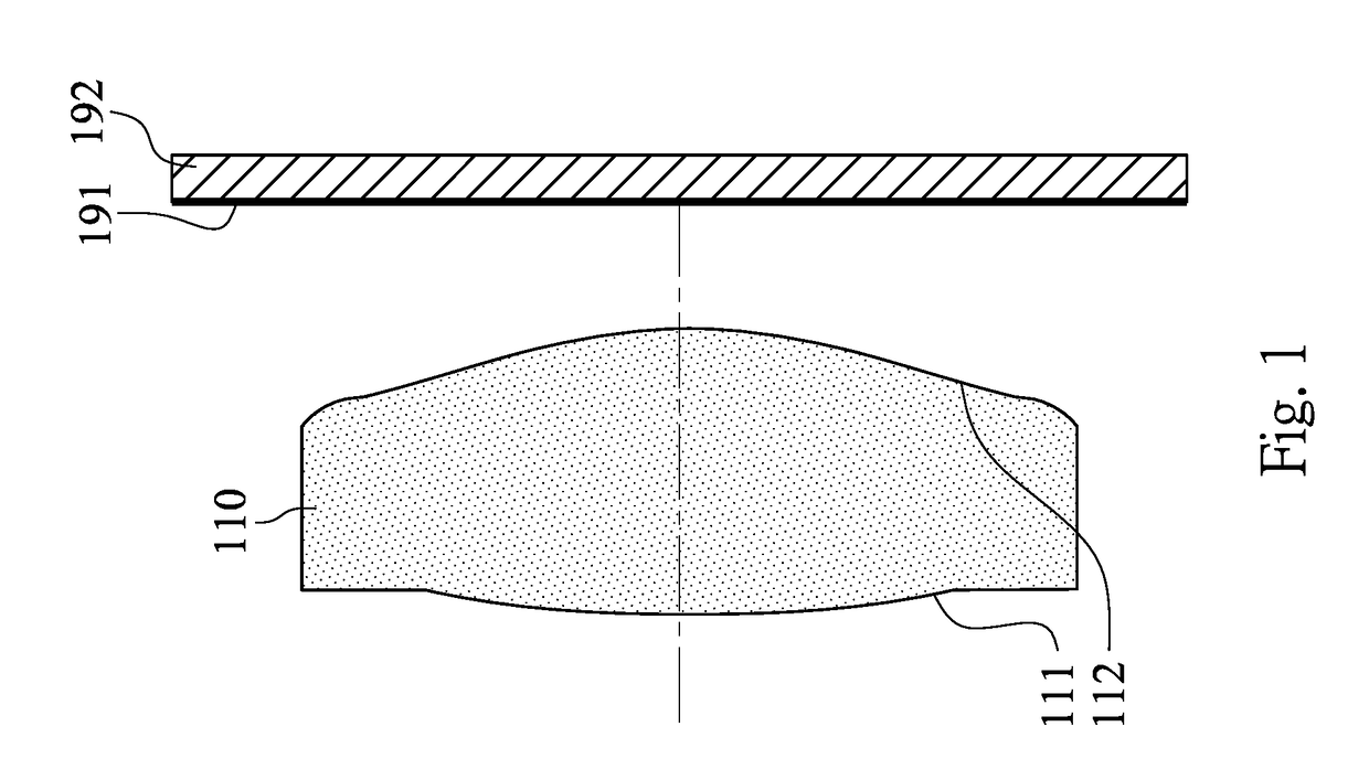
[0083]FIG. 2 is a schematic view of an image capturing apparatus according to the 2nd embodiment of the present disclosure. In FIG. 2, the image capturing apparatus includes an optical image lens assembly (its reference numeral is omitted) and an image sensor 292. The optical image lens assembly includes, in order from an object side to an image side, a first optical lens element 210, a second optical lens element 220 and an image surface 291, wherein the image sensor 292 is disposed on the image surface 291 of the optical image lens assembly. The optical image lens assembly can selectively include other elements, such as an aperture stop (not shown). The other elements are not the key points and will not be described herein.

[0084]The first optical lens element 210 with positive refractive power has an object-side surface 211 being convex in a paraxial region thereof and an image-side surface 212 being concave in a paraxial region thereof, and has the object-side surface 211 and the...

3rd embodiment

[0089]FIG. 3 is a schematic view of an image capturing apparatus according to the 3rd embodiment of the present disclosure. In FIG. 3, the image capturing apparatus includes an optical image lens assembly (its reference numeral is omitted) and an image sensor 392. The optical image lens assembly includes, in order from an object side to an image side, a first optical lens element 310, a second optical lens element 320, a third optical lens element 330 and an image surface 391, wherein the image sensor 392 is disposed on the image surface 391 of the optical image lens assembly. The optical image lens assembly can selectively include other elements, such as an aperture stop (not shown). The other elements are not the key points and will not be described herein.

[0090]The first optical lens element 310 with positive refractive power has an object-side surface 311 being convex in a paraxial region thereof and an image-side surface 312 being convex in a paraxial region thereof, and has th...


PUM

PropertyMeasurementUnit
wavelength rangeaaaaaaaaaa
transmittanceaaaaaaaaaa

Abstract

An optical image lens assembly includes, from an object side to an image side, at least one optical lens element. The optical lens element is made of plastic material and includes a long wavelength light absorbing agent. The long wavelength light absorbing agent is uniformly mixed with the plastic material, wherein the optical lens element has refractive power, and at least one of the object-side surface and the image-side surface thereof is aspheric.

Description

RELATED APPLICATIONS[0001]This application claims priority to Taiwan Application Serial Number 105128965, filed Sep. 7, 2016 and Taiwan Application Serial Number 106127818, filed Aug. 16, 2017, which are herein incorporated by reference.BACKGROUNDTechnical Field[0002]The present disclosure relates to an optical image lens assembly and an image capturing apparatus. More particularly, the present disclosure relates to a compact optical image lens assembly and an image capturing apparatus which can absorb long-wavelength lights and are applicable to electronic devices.Description of Related Art[0003]Mobile products conventionally adopt an image sensor for capturing lights so as to form an image. The most common image sensor is a CCD (Charge-Coupled Device) or a CMOS (Complementary Metal-Oxide-Semiconductor) sensor. However, the image sensor not only receives and responds to visible lights but also responds to infrared lights which is invisible for human eyes. If the infrared lights are...

Claims


Application Information

Patent Timeline
Patent Type & Authority Applications(United States)
IPC IPC(8): G02B5/20G02B5/22G02B1/04G02B9/04G02B9/34
CPCG02B5/208G02B5/223G02B9/34G02B9/04G02B1/041G02B13/0045G02B13/0035G02B13/004C08L69/00
Inventor LAI, MEI-HUI
Owner LARGAN PRECISION
Why Eureka
Try Eureka