Rotor with winding elements and a winding head adjacent to a rotor body for a dynamoelectric machine

a dynamoelectric machine and winding head technology, applied in the direction of windings, magnetic circuit rotating parts, magnetic circuit shape/form/construction, etc., can solve the problems of unusual overall size, insufficient cooling, complex fixing of winding head from constructional and mounting viewpoint, etc., to reduce axial relative movement, improve winding head ventilation, and cool very well

Active Publication Date: 2014-12-30
VOITH PATENT GMBH
View PDF10 Cites 0 Cited by
  • Summary
  • Abstract
  • Description
  • Claims
  • Application Information

AI Technical Summary

Benefits of technology

[0023]It can additionally be provided in a further embodiment of the rotor in accordance with the invention that radially extending openings for through-flow with cooling air are provided in the region of the winding head carrier. Such openings, which can be arranged in the region of the winding head carrier in form of annular interruptions in the winding head carrier or radially extending channels, also improve the ventilation of the winding head. Very good through-flow of the winding elements in the region of the winding head with cooling air is enabled in this way in combination with the area which freely remains between the segmented annular arrangements of the support bodies, so that said winding elements can be cooled very well. Good cooling also allows reducing the axial relative movement of the winding element in relation to the winding head carrier, so that in the case of the aforementioned measures it is merely necessary to ensure that comparatively short paths of axial relative movement are enabled in the components with respect to one another as required.

Problems solved by technology

Such winding head fixing is very complex from a constructional and mounting viewpoint.
Practice has shown that this kind of cooling is insufficient when the bearing boxes—as in the aforementioned German specification—are comparatively large and substantially cover the circumferential area of the winding head.
Although the described configuration allows better cooling of the winding elements in the region of the winding head, it has an exceptionally overall size because sufficient space for radially guiding the tension bolts between the individual winding elements needs to be provided.
Furthermore, it shows decisive disadvantages in air resistance.

Method used


Image

  • Rotor with winding elements and a winding head adjacent to a rotor body for a dynamoelectric machine
  • Rotor with winding elements and a winding head adjacent to a rotor body for a dynamoelectric machine
  • Rotor with winding elements and a winding head adjacent to a rotor body for a dynamoelectric machine

Examples


Embodiment Construction

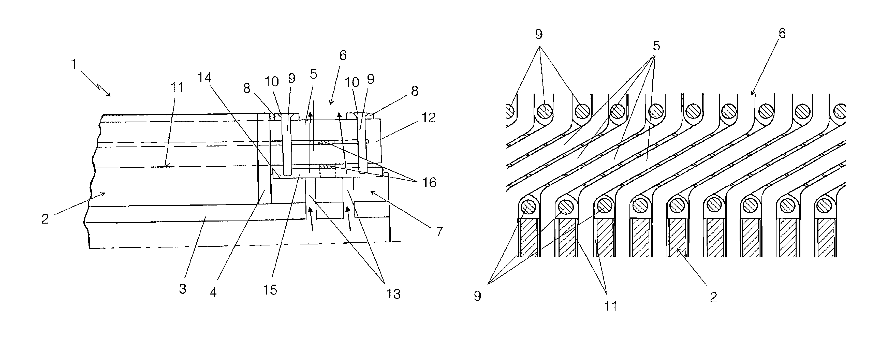
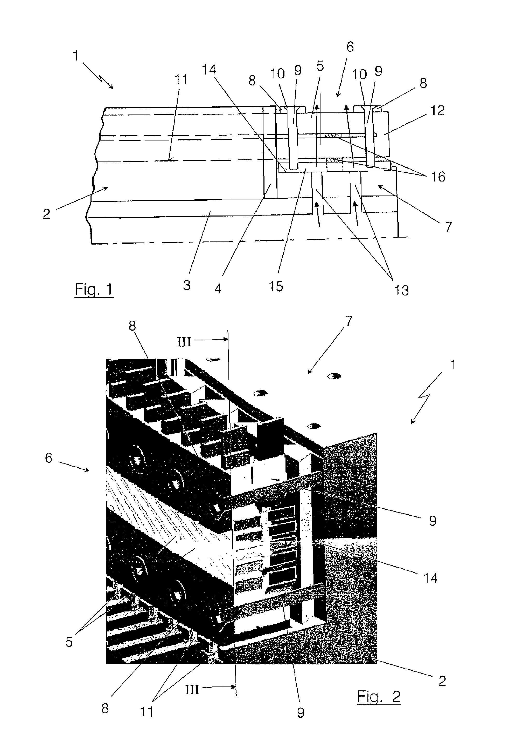
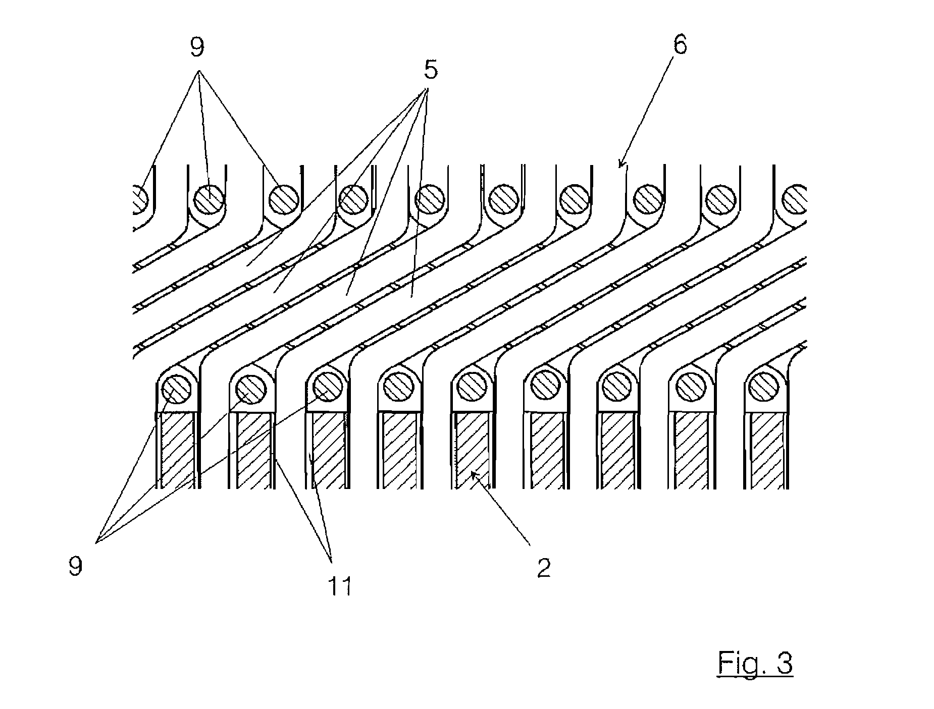
[0028]The illustration of FIG. 1 shows a schematic diagram of a section of a rotor 1 of a dynamoelectric machine. Such a rotor 1 can have an outside diameter which has a magnitude of 3 to 8 m for example. The rotor 1 typically consists of a rotor body 2, which is generally arranged in a laminated manner, i.e. of a plurality of sheets which are stacked on top of one another in the axial direction. The rotor body 2 can be carried for example by a hub 3, as indicated in this case by way of example. In the typical laminated configuration of the rotor body 2, it is axially tensioned by means of a pressure plate 4. Numerous grooves 11 which are distributed over the circumference are provided in the rotor body 2, in which winding elements 5 are arranged in the known manner. The illustration of FIG. 1 does not show the laminated arrangement in the illustration of the rotor body 2. Similarly, the grooves 11 are not recognizable, only the winding elements 5 extending in said grooves are indic...


PUM


Abstract

Provided is a rotor for a dynamoelectric machine. The rotor includes winding elements arranged in axially extending grooves of a rotor body, a winding head arranged axially adjacent to the rotor body, and a winding head carrier, connected to the winding head by means of tension bolts, all arranged in such a way that reliable securing of the winding head against radial expansion due to centrifugal forces is ensured, while resulting in a compact and cost-effective configuration as well as sufficient cooling.

Description

[0001]This is a U.S. national phase application, which is based on, and claims priority from, PCT application Serial No. PCT / EP2011 / 002111, filed Apr. 27, 2011, which claims priority from foreign application Serial No. 10 2010 020 415.3, filed May 12, 2010, in Germany.BACKGROUND OF THE INVENTION[0002]The invention relates to a rotor for a dynamoelectric machine such as an electric generator, according to the kind as defined in closer detail in the preamble of claim 1.[0003]For the purpose of fastening winding heads of rotor windings it is common practice among other things to support the winding heads on the inside by an annular winding head carrier and to fix the winding heads to said winding carrier by means of binding bands. Especially in the case of larger machines it is also possible to use a ring divided several times instead of a binding band, which ring rests with intermediate insulating layers on the winding heads and is fixed by means of screws to the winding carrier. Caps...

Claims


Application Information

Patent Timeline
Patent Type & Authority Patents(United States)
IPC IPC(8): H02K3/46H02K3/00H02K3/51
CPCH02K3/51
Inventor HENNING, HOLGEREILEBRECHT, PHILIPPVESER, STEFANHILDINGER, THOMAS
Owner VOITH PATENT GMBH
Why Eureka
Try Eureka