Control panel support mechanism, control panel assembly, and image forming apparatus

a technology of control panel and support mechanism, which is applied in the direction of electrical apparatus casing/cabinet/drawer, instruments, applications, etc., can solve the problems of control panel sliding downwards, locking lugs slipping against the upper or lower edges of locking holes, so as to prevent the control panel from vibrating for an extended period of time. , to achieve the effect of reliable prevent the effect of sliding downwards

Inactive Publication Date: 2014-12-30
KONICA MINOLTA BUSINESS TECH INC
View PDF7 Cites 1 Cited by
  • Summary
  • Abstract
  • Description
  • Claims
  • Application Information

AI Technical Summary

Benefits of technology

[0013]It is a first object of the present invention to provide a control panel support mechanism that reliably prevents the control panel from vibrating over an extended period of time. It is a second object of the present invention to provide a control panel assembly and an image forming apparatus that include such a control panel support mechanism.

Problems solved by technology

However, even this structure has the problem that if an unreasonable force is applied to the input control unit in the control panel so as to swing the control panel downwards, the locking lug will swing downwards in the locking hole, causing the control panel to swing downwards.
Furthermore, when the locking lug is inserted into or extracted from the locking holes, the locking lug may slide against the upper or lower edges of the locking holes.
Accordingly, the locking lug, as well as either or both of the vertical edges of the locking holes, will become worn over time if the locking lug is repeatedly inserted into and extracted from the locking holes.
This will increase the space between the locking lug and the locking holes, resulting in the control panel being swung downwards upon application of a large force.

Method used


Image

  • Control panel support mechanism, control panel assembly, and image forming apparatus
  • Control panel support mechanism, control panel assembly, and image forming apparatus
  • Control panel support mechanism, control panel assembly, and image forming apparatus

Examples


Embodiment Construction

[0032]Structure of Image Forming Apparatus

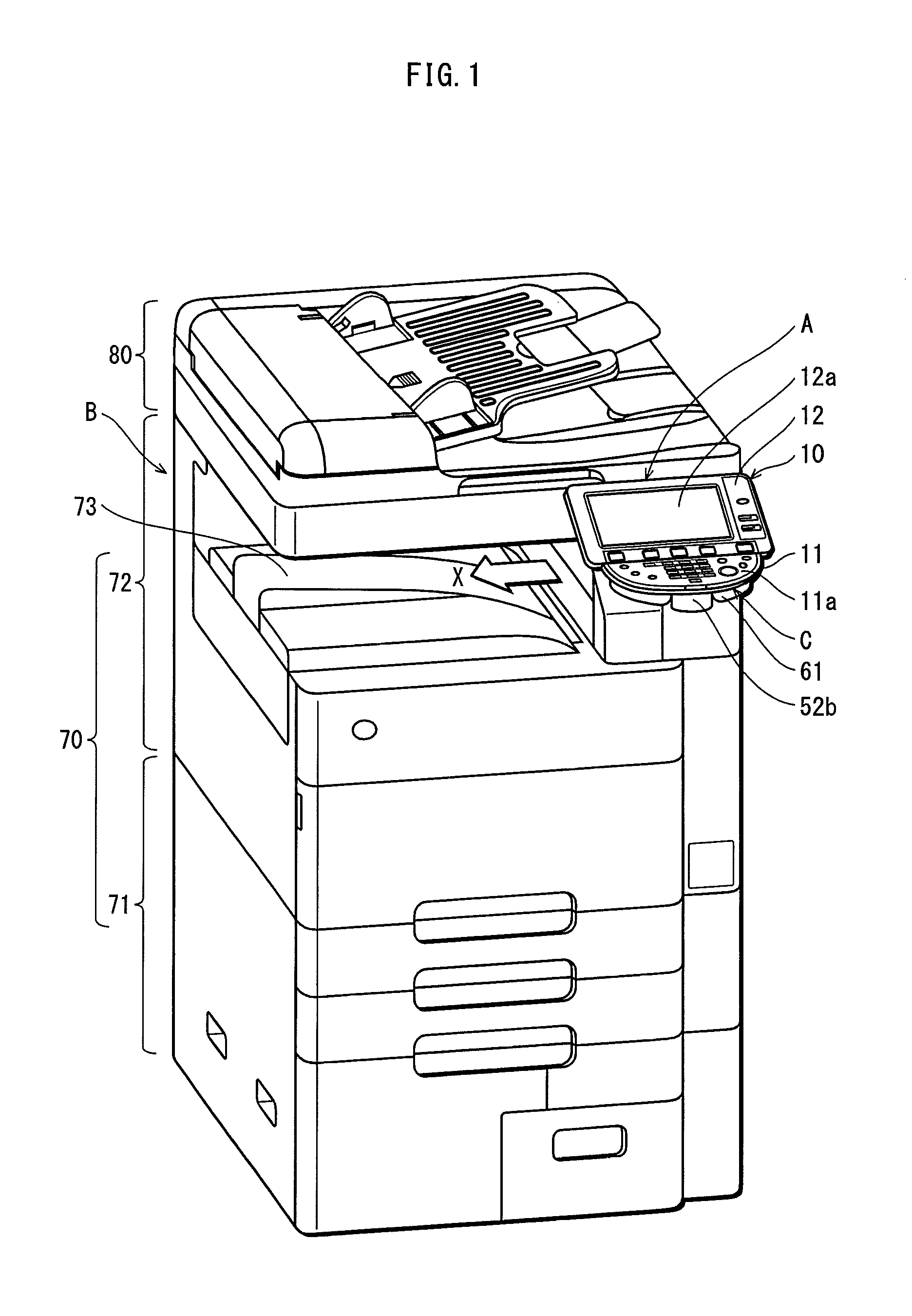
[0033]FIG. 1 is a perspective view of an image forming apparatus formed by a control panel assembly A and an image forming apparatus body B. A control panel in the control panel assembly A is supported by a control panel support mechanism according to the embodiment of the present invention.

[0034]The image forming apparatus body B forms an image on a recording sheet by well-known electrophotography and includes an image forming unit 70 and an image reading unit 80 provided above the image forming unit 70. The image forming unit 70 includes a paper tray 71 at the lowest part the body B for storing recording sheets and an image forming subunit 72 provided above the paper tray 71 for forming a toner image on a recording sheet fed from the paper tray 71.

[0035]On the upper surface of the image forming unit 70, between the image forming unit 70 and the image reading unit 80, a sheet ejection unit 73 is formed for ejecting a recording sheet on whic...


PUM


Abstract

Provided is a control panel support mechanism having a first support member attached to an image forming apparatus, a second support member supporting a control panel and axially supported by the first support member to be vertically swingable with respect to the first support member, a lock member slidable towards or away from a swing axis of the second support member, and a biasing unit to bias the lock member to slide towards the swing axis. The first support member has a plurality of engaging grooves each positioned along a radial direction with respect to the swing axis and having an opening at an end of the first support member opposite the swing axis, the plurality of engaging grooves being aligned vertically. The biasing unit biases the lock member so that the lock member enters one of the plurality of engaging grooves through the opening to lock in engagement with the engaging groove.

Description

[0001]This application is based on an application No. 2010-74310 filed in Japan, the contents of which are hereby incorporated by reference.BACKGROUND OF THE INVENTION[0002](1) Field of the Invention[0003]The present invention relates to a control panel support mechanism mounted on an image forming apparatus to support a control panel, to a control panel assembly in which a control panel is supported by such a control panel support mechanism, and to an image forming apparatus provided with such a control panel assembly.[0004](2) Description of the Related Art[0005]Image forming apparatuses such as copiers or printers, as well as image reading apparatuses such as scanners, are sometimes provided with a large control panel that integrates an input control unit and a display unit. The input control unit is for inputting a variety of information, and the display unit displays the input information, the operational status of the device, etc. Patent Literature 1 (Japanese Patent Applicati...

Claims


Application Information

Patent Timeline
Patent Type & Authority Patents(United States)
IPC IPC(8): G03G15/00
CPCG03G15/5016
Inventor UCHIDA, NAOTAKAYAMAMURA, AKIRASAWADA, KENJI
Owner KONICA MINOLTA BUSINESS TECH INC
Why Eureka
Try Eureka