Vibration piezoelectric acceleration sensor

a piezoelectric acceleration and sensor technology, applied in the direction of acceleration measurement using interia force, instruments, and the details of semiconductor/solid-state devices, can solve the problems of increasing the cost of the device, affecting the performance of the device, and detecting static gravitational acceleration components

Inactive Publication Date: 2009-09-15
PANASONIC CORP
View PDF13 Cites 0 Cited by
  • Summary
  • Abstract
  • Description
  • Claims
  • Application Information

AI Technical Summary

Benefits of technology

[0009]This invention includes an element comprising a frame, a pair of beam shaped members linearly and oppositely disposed on the frame, an under part electrode which is successively stacked on the beam shaped member, a piezoelectric thin film, an upper part electrode, a support body supporting the beam shaped members at an adjacent one end of each beam shaped member, and a holding part holding the support body slidably in a linear direction, in which the beam shaped members are extended and retracted by an acceleration transmitted to the support body through the holding part of the element, and in which the acceleration is detected through a change in a natural oscillation frequency of the beam shaped member. A pair of beam shaped members are linearly and oppositely disposed crossing the pair of beam shaped members that is linearly and oppositely disposed on the frame, detecting the acceleration in two axes directions. With this arrangement, both static and dynamic acceleration can be detected along two axes directions without being affected by noise or other environmental change. Thus, a highly reliable vibration piezoelectric acceleration sensor which operates under severe temperature changing environment is provided.

Problems solved by technology

However, in this device, accurate acceleration detection is difficult because the variance in the change of the resistance value is wide and signals are affected by a change in the temperature of the processing circuits.
With the device in JP '075, where the piezoelectric element is used for detecting displacement speed of the element, detecting of such as a component of static gravitational acceleration is difficult because of its detecting mechanism.
Thus, cost increase and possible variation in performance exist.

Method used


Image

  • Vibration piezoelectric acceleration sensor
  • Vibration piezoelectric acceleration sensor
  • Vibration piezoelectric acceleration sensor

Examples


first exemplary embodiment

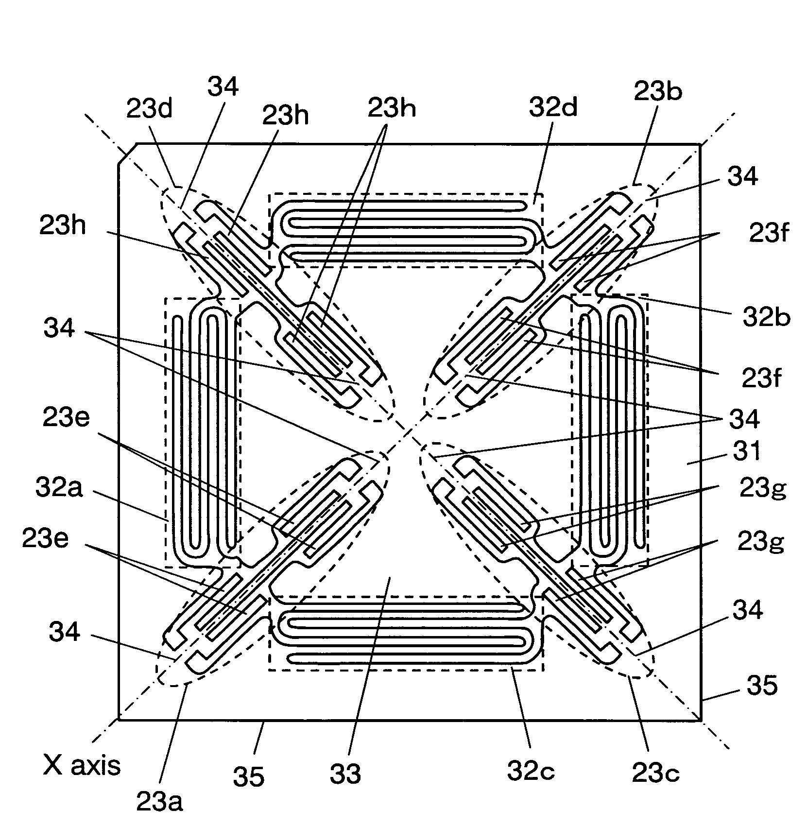
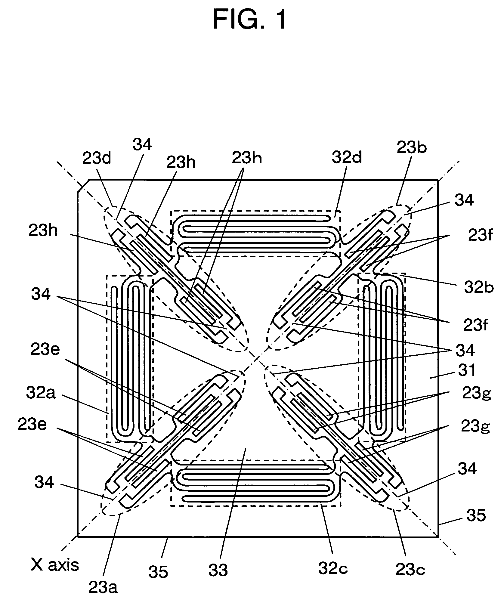
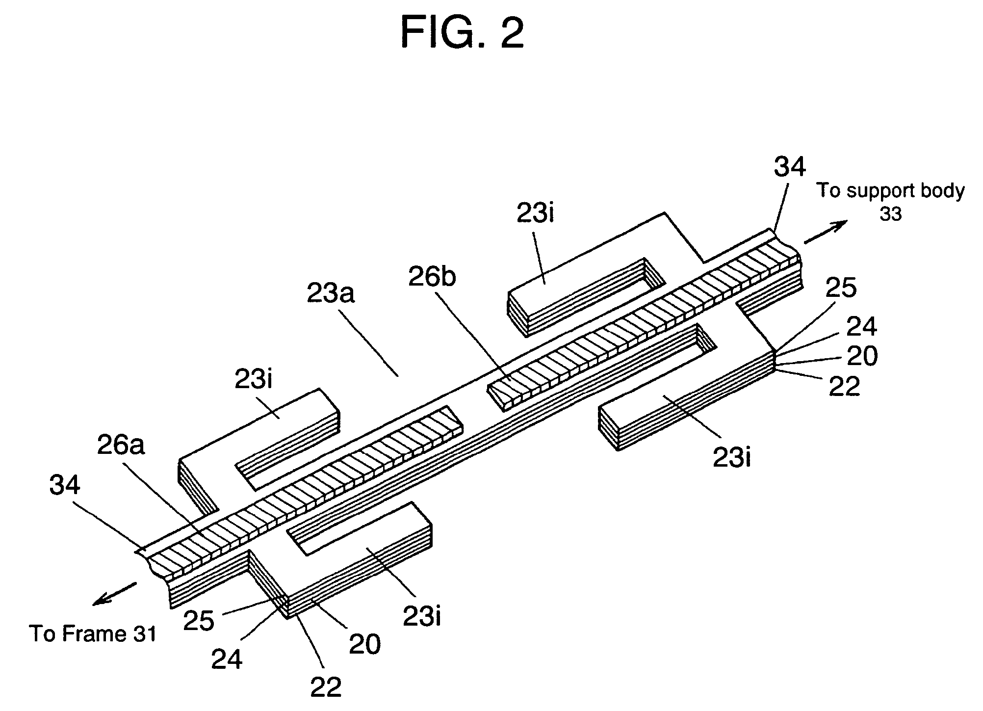
[0059]As shown in FIGS. 1 and 2, beam shaped members 23a to 23d having a natural oscillation frequency are disposed in frame 31. Support body 33 changes the natural oscillation frequency of beam shaped members 23a to 23d. Holding parts 32a to 32d are formed in a meandering manner for holding the support body in a moveable manner and in a linear direction. In this embodiment, beam shaped members 23a to 23d extend and retract freely, therewith acceleration can be detected in a highly responsive and a highly accurate manner without being affected by a change in temperature.

[0060]Beam shaped member 23a is formed in a generally rectangular shape and has basal part 34 at each end of the beam shaped member, one basal part 34 being held by frame 31 and an other basal part 34 being held by support body 33. Support body 33 is held by frame 31 via holding part 32a formed in the meandering manner, thus moving back-and-forth in a linear direction. Here, only beam shaped member 23a disposed on fr...

second exemplary embodiment

[0079]FIG. 6 shows an airbag control system, an application example of VAS 41 of the invention. VAS 41 is installed in the X-axis and the Y-axis directions. The control system is explained with reference to vehicle body 44, front airbag 45, side airbag 46, opening device 47 and driver 48. Arrow mark 49 indicates a moving direction of the vehicle.

[0080]Thus installed, VAS 41 of the present invention controls work in vehicle 44 by controlling acceleration. When an acceleration value exceeds a certain level, the sensor sends out an acceleration output signal to airbag opening device 47 for opening the airbag. The opening signal is then transmitted to airbags 45 and 46 opening the airbag, thus realizing safe driving with the sensor.

[0081]If acceleration is generated by a collision in the moving direction (X-axis direction), front airbag 45 is opened, and if acceleration is generated in a side direction (Y-axis direction), the acceleration signal in right and left directions opens side a...


PUM


Abstract

A vibration piezoelectric acceleration sensor including a pair of beam shaped members linearly and oppositely disposed on a frame, a support body supporting the beam shaped member, and a holding part holding the support body moveably in a linear direction, and another pair of beam shaped members disposed linearly and oppositely crossing the pair of beam shaped members detecting acceleration in two axes, i.e. X and Y directions. The beam shaped members are extended and retracted by the acceleration transmitted to the support body through the holding part, changing a natural oscillation frequency. Accordingly, a high change ratio of resonance frequency can be provided with the detection of the acceleration, and the acceleration in the direction of two axes can be detected without being affected by a change in temperature.

Description

[0001]This application is a U.S. national phase application of PCT International Application PCT / JP2005 / 002126TECHNICAL FIELD[0002]The present invention relates to a vibration piezoelectric acceleration sensor (hereinafter, called VAS) to be used for a posture controller, and a vehicle and other mobile equipment control system.BACKGROUND ART[0003]FIG. 7 is a cross sectional view of a conventional acceleration sensor. As shown in FIG. 7, diaphragm 2 is formed in a rear side of chip 1, and a plurality of distortion sensing resistors 3 are disposed on a surface side of the chip, (i.e., an opposing side of the diaphragm from the rear side). At another portion of the surface side of chip 1, a semiconductor integrated circuit for computing acceleration, and thin film resistor 4 for adjusting performance of the semiconductor integrated circuit are disposed. Protection film 5 is formed on the surface side covering at least thin film resistor 4 but not covering distortion sensing resistors 3...

Claims


Application Information

Patent Timeline
Patent Type & Authority Patents(United States)
IPC IPC(8): G01P15/10G01P15/09G01P15/097G01P15/18H01L21/56H01L23/28
CPCG01P15/09G01P15/18G01P15/097G01P2015/084
Inventor TERADA, JIRONAKATANI, MASAYAISHIDA, TAKAMI
Owner PANASONIC CORP
Why Eureka
Try Eureka