Ink storing unit for a hand-operated stamp

a technology of hand-operated stamps and storage units, which is applied in the direction of printing presses, cylinder presses, printing, etc., can solve the problems of insufficient possibility, and achieve the effect of ensuring sufficient impregnation of printing plates

Active Publication Date: 2015-01-06
COLOP STEMPELERZEUGUNG SKOPEK GMBH & CO KG
View PDF31 Cites 10 Cited by
  • Summary
  • Abstract
  • Description
  • Claims
  • Application Information

AI Technical Summary

Benefits of technology

[0010]The object of the present invention is to provide an ink storage unit for a hand stamp of the initially-defined kind, which enables a structurally simple and permanently reliable fixation of the storage body within the retainer.
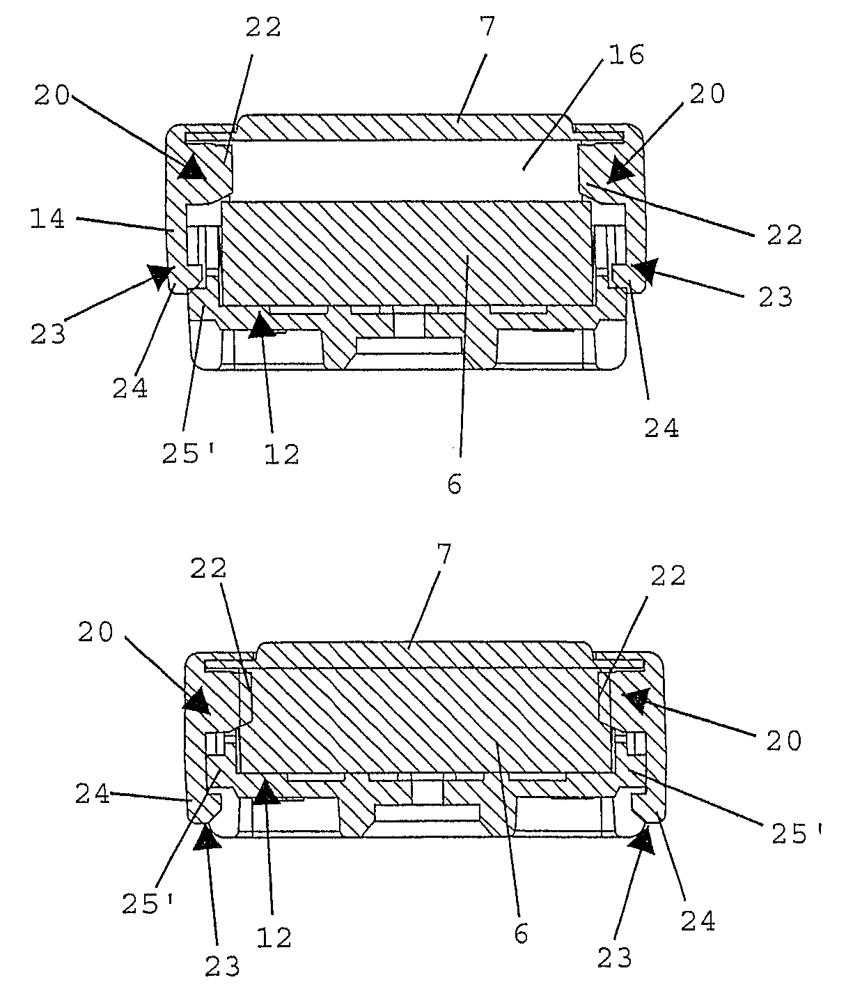
[0011]In accordance with the invention, this is achieved in that the storage body is fixed in the retainer by at least one engaging part. The engaging part enables the immovable fixation of the storage body within the retainer as soon as the engaging part enters into engagement with the storage body. An unreliable adhesive connection can thus advantageously be renounced. The fixation according to the invention, of the storage body with the engaging part is not subject to any limitations as to the selection of materials for the retainer, which has disadvantageously been the case with the known adhesive connections. In a preferred embodiment, the engaging part at least partially penetrates into the storage body, thus establishing a frictional and positive connection between the engaging part and the storage body. Alternatively, it will be advantageous, in particular where damage to the storage body is to be avoided, if the engaging part merely causes a local elastic deformation of the storage body during the engagement of the storage body and the fixation of the storage body is predominantly realized by a frictional engagement.
[0014]In order to protect the printing plate from damage and contamination by dust particles or the like, it will be beneficial if a transparent protective foil is provided on the side of the printing plate facing away from the storage body. In that the protective foil is translucent, it may be left on the printing plate during exposure, thus advantageously preventing the printing plate from being soiled.
[0018]In a structurally simple configuration involving low production costs, it is provided that at least one snap-in element is comprised of two snap-in projections arranged one after the other in the transfer direction and preferably also mutually offset laterally, and at least one snap-in element cooperating therewith is formed by a snap-in hook, preferably a snap-in hook shared by the two snap-in projections, which overlaps one of the two snap-in projections as a function of the snap-in position. If the snap-in elements, or the frame and the retainer, are made of a synthetic material by injection molding, as is preferably the case, manufacturing advantages will be feasible by the lateral offset of the snap-in projections. The mentioned snap-in elements in the form of snap-in projections or snap-in hooks can be combined in any manner whatsoever; thus, it is, for instance, also possible to assign a separate snap-in hook to each of the snap-in projections. In a preferred manner, the snap-in projections are provided on the retainer and are overlapped by a single and accordingly wide snap-in hook provided on the frame. It may also be contemplated to interchange the positions of the snap-in projections and the snap-in hook such that the snap-in projections are disposed on the frame and the snap-in hook is disposed on the retainer.
[0020]In known hand stamps of the present type, it has been observed that the contact pressure by which the text plate and the storage body are pressed against each other during the exposure and thereafter is non-uniformly distributed due to unevennesses in the text plate, which may lead to an insufficient impregnation with ink at certain points of the text plate. In order to overcome this problem of known flash hand stamps and ensure the uniform application of pressure to the printing plate, it will be advantageous if an, in particular, softly elastic pressing plate, e.g. of polyurethane foam, is provided on the side of the printing plate facing away from the storage body, optionally separated by the transparent protective foil. The softly elastic pressing plate causes a constant contact pressure to be exerted over the entire surface of the printing plate, thus safeguarding sufficient impregnation of the printing plate with ink from the storage body. In this respect it has turned out to be of particular advantage if the pressing plate is pressed against the printing or text plate for a defined time exceeding the period of exposure, e.g. a total of ten minutes, in order to ensure thorough impregnation.
[0021]For the compact and protected arrangement of the individual components of the ink storage unit, it will be beneficial if, on the side of the pressing plate facing away from the printing plate, a cover is provided via an interposed, projecting strip of paper. Said strip of paper might also serve as an indicator that no thorough impregnation has yet occurred at the storage unit. After the printing plate has absorbed sufficient ink, the strip of paper can be removed to indicate that the ink storage unit is ready for making a print.

Problems solved by technology

In the shown ink storage unit, the fixed fastening by gluing of the ink storage in its retaining part is disadvantageous, since the adhesive connection may come loose during operation, or gluing will not be possible, or only insufficiently possible, when using certain synthetic materials like polypropylene etc. for the retaining parts.

Method used


Image

  • Ink storing unit for a hand-operated stamp
  • Ink storing unit for a hand-operated stamp
  • Ink storing unit for a hand-operated stamp

Examples


Embodiment Construction

[0036]FIG. 1 depicts a pre-inked hand stamp 1 including a (stamp) housing 2 and an actuating unit 3 and having a structure known per se, cf., e.g., AT 503 112 B1. To the lower side of the housing 2 is fastened a cover 4 protecting an ink storage unit 5 received in the interior of the housing 2 and comprising a printing plate 7 that is fed with ink by a storage body 6. The hand stamp 1 is illustrated in a state ready for delivery, which is indicated by a strip of paper 8 disposed on the inner side of the cover 4 and laterally projecting out of the housing 2.

[0037]In order be able to use the illustrated hand stamp 1, the cover 4 and a pressing plate 9 temporarily attached to the housing 2 and explained in more detail below in connection with the production of the printing plate 7 have to be removed.

[0038]To transfer the printing plate 7 from a resting position retracted in the housing 2 into a printing position, the actuating unit 3 is downwardly displaced against the action of a spri...


PUM


Abstract

An ink-storage unit for a hand stamp includes a retainer in which a storage body is arranged, and a frame in which a printing plate is arranged. The frame sits in a provisional mounting position on the retainer, in which position the storage body and the printing plate are held at a distance from each other, and the frame can be moved into a final mounting position on the retainer, in which position the storage body and the printing plate lie against each other, wherein the storage body is fixed in the retainer by at least one engaging part.

Description

CROSS-REFERENCE TO RELATED APPLICATIONS[0001]This application is a continuation of U.S. patent application Ser. No. 13 / 521,150, filed on Jul. 9, 2012, which is the National Stage of PCT / AT2011 / 000043 filed on Jan. 27, 2011, which claims priority under 35 U.S.C. §119 of Austrian Application No. A 109 / 2010 filed on Jan. 27, 2010, the disclosure of which is incorporated by reference. The international application under PCT article 21(2) was not published in English.BACKGROUND OF THE INVENTION[0002]The invention relates to an ink-storage unit for a hand stamp, including a retainer in which a storage body is arranged, and a frame in which a printing plate is arranged, wherein in a provisional mounting position the frame sits on the retainer, in which position the storage body and the printing plate are held at a distance from each other, and the frame can be moved into a final mounting position on the retainer, in which position the storage body and the printing plate lie against each ot...

Claims


Application Information

Patent Timeline
Patent Type & Authority Patents(United States)
IPC IPC(8): B41F3/00B41K1/38B41K1/42B41K1/02B41K1/40B41K1/50B41K1/54
CPCB41K1/54B41K1/02B41K1/38B41K1/40B41K1/50
Inventor FABER, ERNST
Owner COLOP STEMPELERZEUGUNG SKOPEK GMBH & CO KG
Why Eureka
Try Eureka