

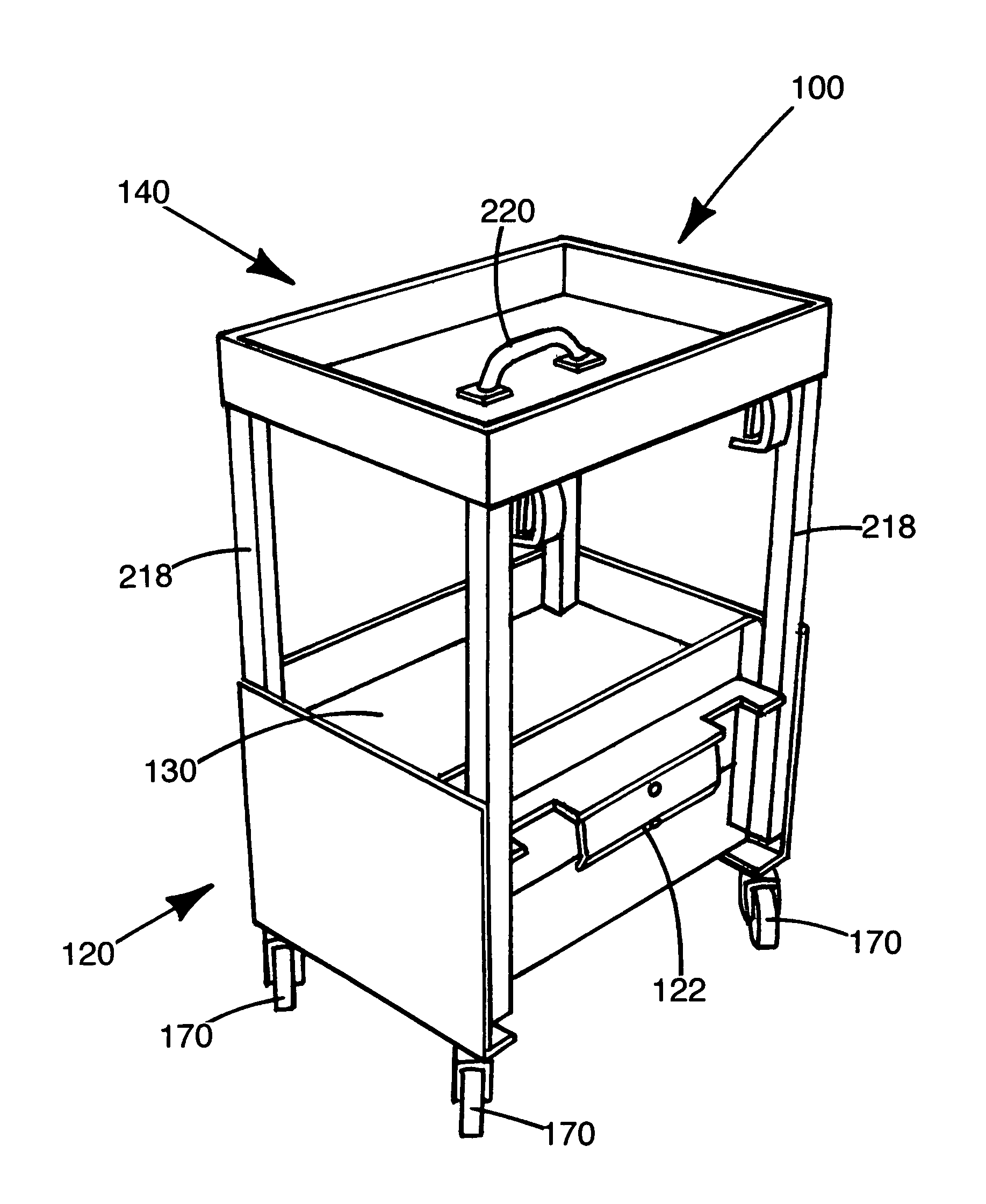
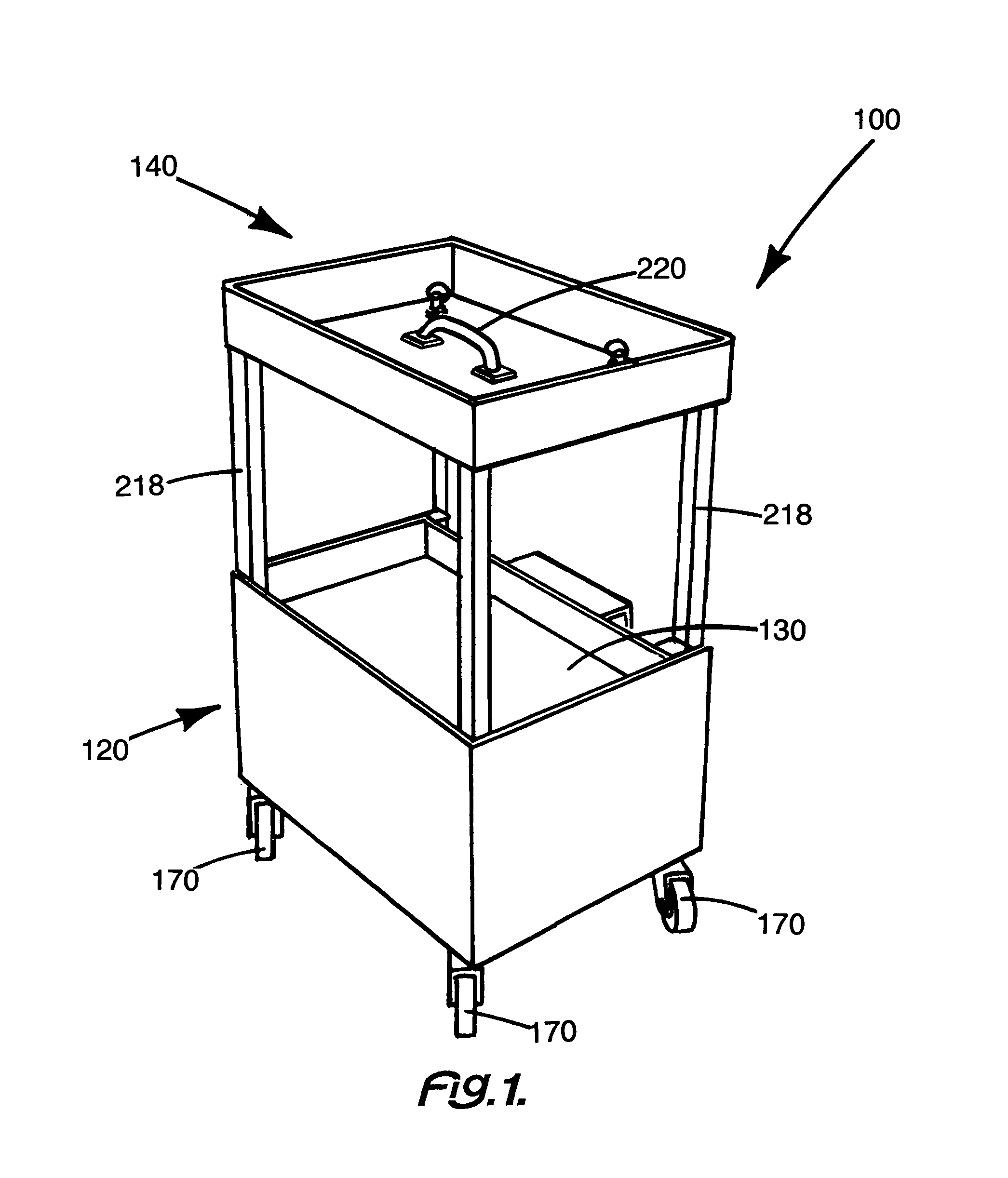
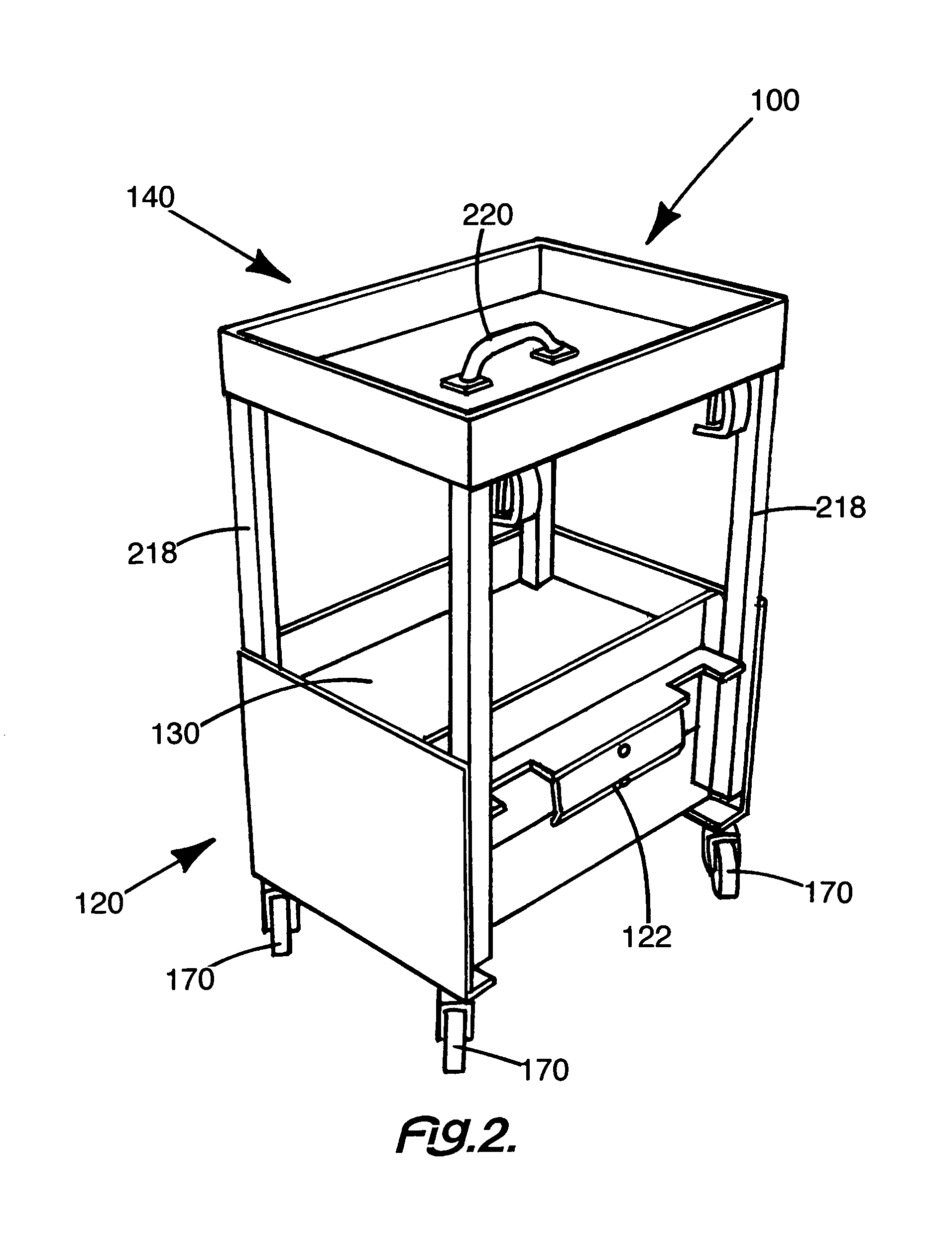
Utility holding device
a technology of holding device and holding device, which is applied in the direction of hand carts, transportation and packaging, building scaffolds, etc., can solve the problems of difficult design of appropriate devices to achieve the goal of achieving the goal, inherently dangerous work on any building, and device, which works for one set of materials or tools, may not work for other sets of tools and materials, etc., to achieve the effect of safe use and safe use of ladders
- Summary
- Abstract
- Description
- Claims
- Application Information
AI Technical Summary
Benefits of technology
Problems solved by technology
Method used
Image

Examples
second embodiment
[0083]In FIG. 23, telescopic is assemblies 230, flexible length risers 244, can be clearly seen. Flexible length risers 244 are generally four in number and are positioned at each corner of utility holding device 100. Flexible length risers 244 hold top compartment tray 140 in various positions relative to base 120. Such positions include lowered position 248 (FIG. 21) and raised position 228 (FIG. 20). Such flexibility adds greatly to the functionality of the utility holding device 100.
[0084]Flexible length risers 244 move in and out of fixed tube 246. Fixed tube 246 has a locking pin aperture 242 and flexible length riser 244 has a plurality of locking pin apertures 242. Flexible length riser 244 is moved into or out of fixed tube 246 to a desired position and a locking pin aperture 242 on each is aligned and secured with locking pin 240. This allows the top compartment tray 140 to be secured to the base 120 at a variety of positions.
[0085]Turning now to FIG. 24, the flexibility o...
embodiment 350
[0098]Now adding FIG. 40, FIG. 41, FIG. 42, and FIG. 43 to the consideration, the structure and function of bucket embodiment 350 of utility holding device 100 can be clearly seen. In this embodiment, aperture tray 370 replaces top compartment tray 140 as the top segment.
[0099]As seen in FIG. 23, top compartment tray 140 may be connected to base 120 through the cooperation of locking pin 240 and locking pin apertures 242. To remove top compartment tray 140, locking pin 240 is released from the preferably four locking pin apertures 242. Then the preferably four flexible length risers 244 are pulled out of and removed from the corresponding fixed tubes 246.
[0100]Once top compartment tray 140 is removed, aperture tray 370 can be attached. The preferably four flexible length risers 244 of aperture tray 370 are inserted into the corresponding fixed tubes 246 in a male to female relationship. The flexible length risers 244 are inserted into the fixed tubes 246 until the aperture tray 370 ...
PUM
 Abstract
Description
Claims
Application Information