Method and apparatus for gas cylinder sealing

a gas cylinder and sealing technology, applied in the direction of containers, caps, applications, etc., can solve the problems of undesirable gas loss in the process of connecting the cylinder to the gas delivery mechanism, and achieve the effect of eliminating any chance wear and improving the sealing

Active Publication Date: 2015-01-06
CORAVIN
View PDF64 Cites 44 Cited by
  • Summary
  • Abstract
  • Description
  • Claims
  • Application Information

AI Technical Summary

Benefits of technology

[0005]Many commercially available compressed gas cylinders are necessarily high pressured and relatively low volume, and thus any loss of gas in the process of connecting the cylinder to a gas delivery mechanism is undesirable. One or more embodiments of the invention described herein provide for an improved seal between a cylinder and the gas delivery mechanism. The seal may be operable to prevent the initial loss of gas as the cylinder is being opened via a piercing element and further provide a long lasting seal that resists the loss of gas over long periods of time, such as during storage of the gas delivery mechanism. Also, because a gasket may be mounted on or otherwise coupled to the cylinder and not the gas delivery mechanism, the gasket may be replaced with a new gasket when a new cylinder is installed, thus eliminating any chance wear due to repeated use.
[0013]The gasket may be arranged to have any suitable features, such as those discussed above, including an upper opening and a raised semi-circular ring surface with a radius of curvature at an upper portion of the gasket. The gasket and the receiver opening may be arranged to have a face and / or gland seal that is strengthened as the neck is further advanced into the receiver opening, e.g., the upper end face may deform to conform with said bottom surface of the receiver opening thereby forming a stronger seal.

Problems solved by technology

Many commercially available compressed gas cylinders are necessarily high pressured and relatively low volume, and thus any loss of gas in the process of connecting the cylinder to a gas delivery mechanism is undesirable.

Method used


Image

  • Method and apparatus for gas cylinder sealing
  • Method and apparatus for gas cylinder sealing
  • Method and apparatus for gas cylinder sealing

Examples


Embodiment Construction

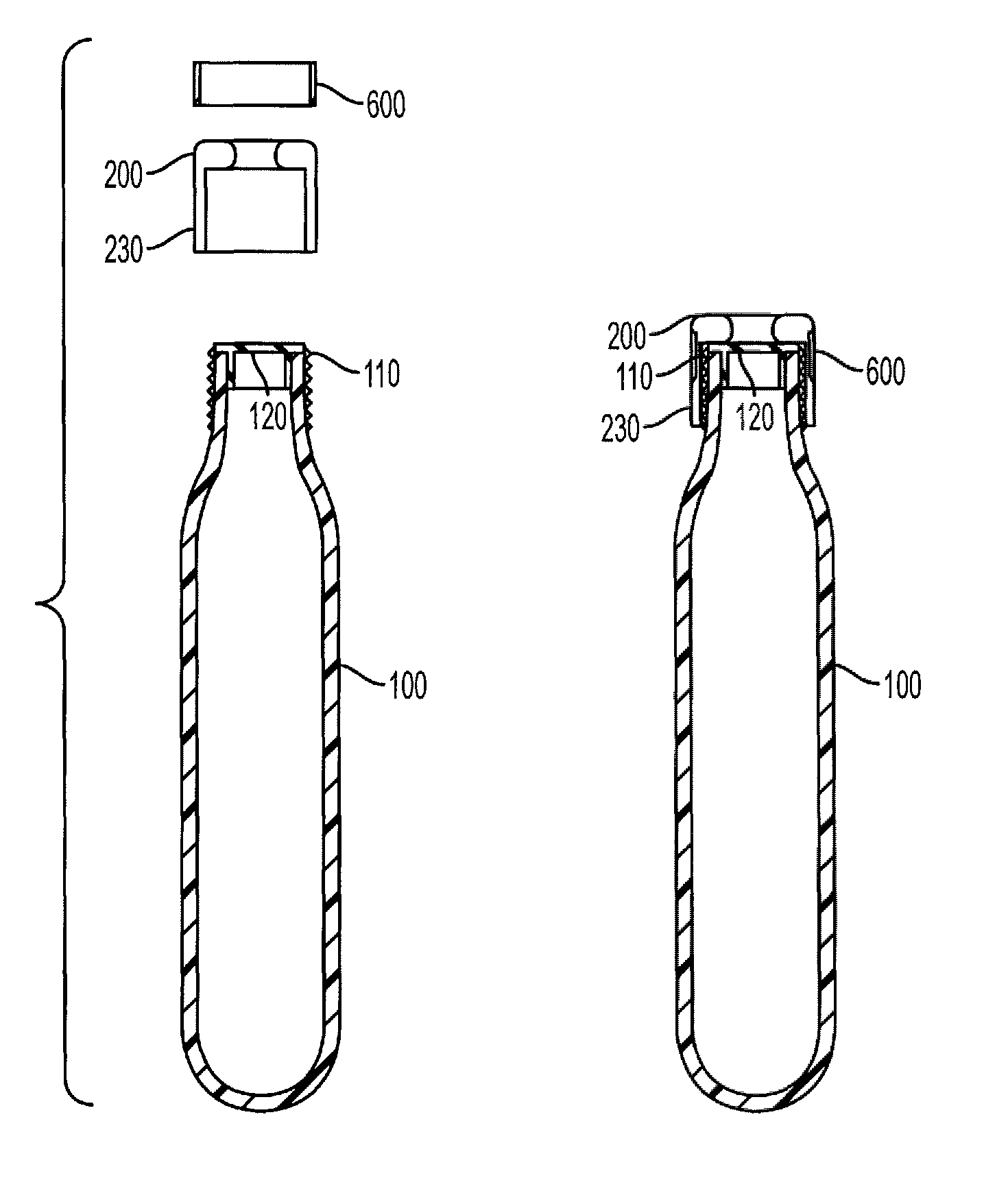
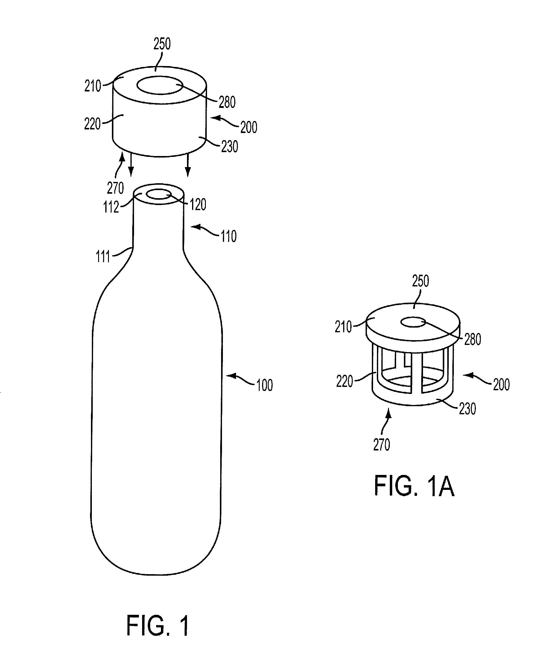
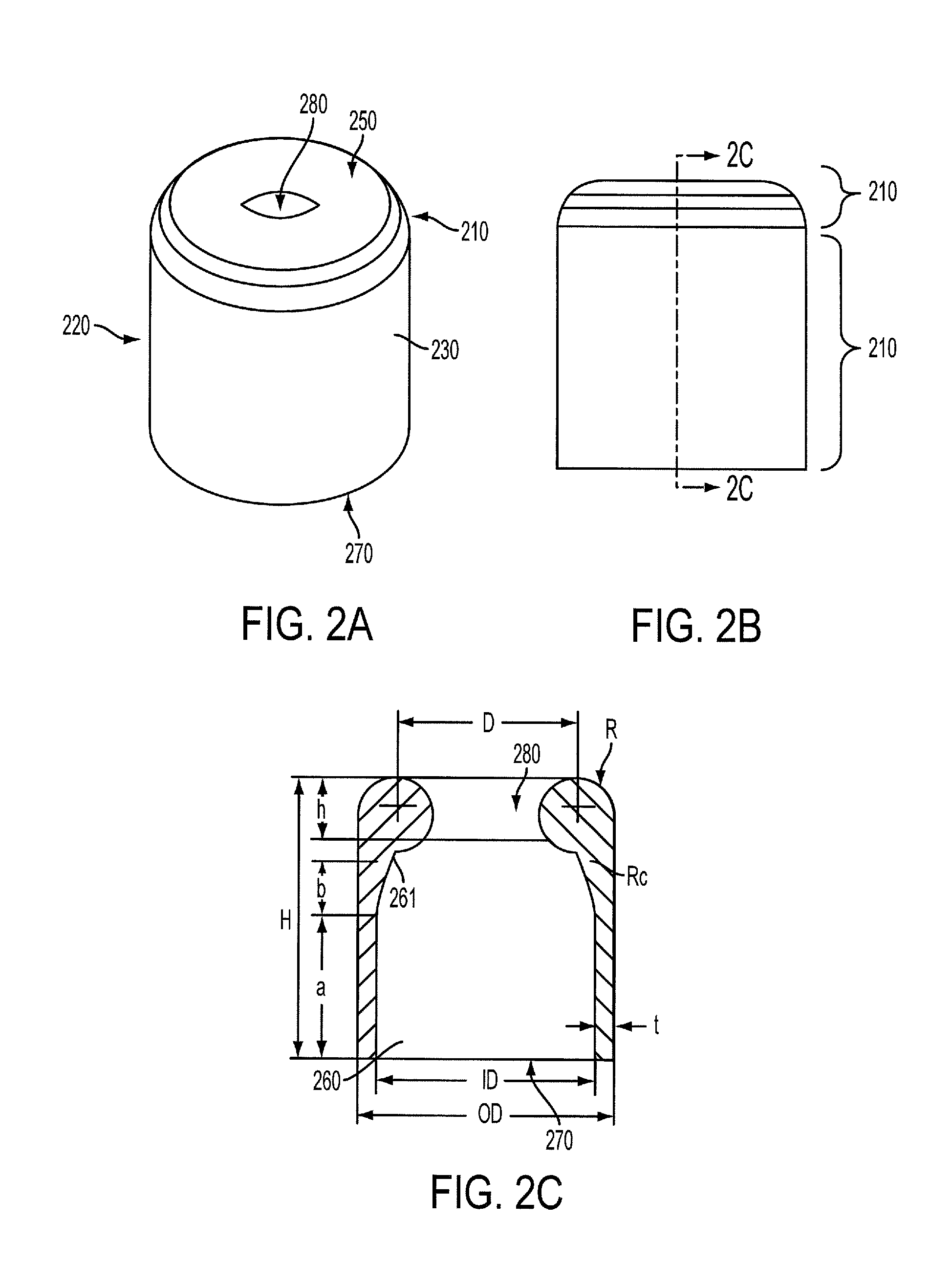
[0039]Various aspects of the invention are described with reference to embodiments of a gasket for interacting with at least a portion of a neck of a gas cylinder, e.g., to provide both a lateral, or side, gland seal and a face seal. Some embodiments are able to provide a gland seal that allows for axial and / or rotational translation of a cylinder neck within a receiving opening while still maintaining a gas-tight seal to prevent or otherwise resist the unwanted release of compressed gas. Maintaining a seal while permitting axial translation may be important in some applications, e.g., to allow the cylinder neck to be advanced against a piercing element that creates an opening in a cap or end piece at the gas outlet of the cylinder neck as the gas cylinder moves axially relative to the piercing element. As a result, gas leakage may be resisted during the cylinder piercing process, if piercing is used. Further embodiments may provide for a face sealing component of the gasket that pr...


PUM

PropertyMeasurementUnit
pressureaaaaaaaaaa
thicknessaaaaaaaaaa
diameteraaaaaaaaaa

Abstract

A gasket for a compressed gas cylinder arranged to operate with a gas cylinder having a neck with a top surface around a gas outlet and a side surface extending downwardly from the top surface. The gasket may include an upper portion arranged for positioning on the top surface of the cylinder and for making a seal with the top surface, and a lower portion extending downwardly from the upper portion and around the side surface of the neck of the cylinder, such that the lower portion is arranged to make a seal with the side surface of the gas cylinder. Face and gland seals may be established by the gasket with an opening that receives the gasket and an associated cylinder neck.

Description

BACKGROUND[0001]1. Field of Invention[0002]This disclosure relates gaskets or sealing members for use with compressed gas canisters, cylinders or containers.[0003]2. Related Art[0004]The coupling of a compressed gas cylinder, canister or other container (herein referred to as a cylinder) with gas delivery mechanisms that use gas supplied by the cylinder often involves an O-ring or other seal element. Such seal elements are used to help prevent leakage of gas, and are described in U.S. Pat. No. 4,694,850, for example.SUMMARY[0005]Many commercially available compressed gas cylinders are necessarily high pressured and relatively low volume, and thus any loss of gas in the process of connecting the cylinder to a gas delivery mechanism is undesirable. One or more embodiments of the invention described herein provide for an improved seal between a cylinder and the gas delivery mechanism. The seal may be operable to prevent the initial loss of gas as the cylinder is being opened via a pier...

Claims


Application Information

Patent Timeline
Patent Type & Authority Patents(United States)
IPC IPC(8): B65D45/32B65D41/50B65D43/04B65D43/08B65D39/04B65D51/16B65D47/36F17C13/06F16J15/02
CPCF16J15/02F17C13/06F17C2205/0308F17C2201/058F17C2205/0305F17C2205/032F17C2221/011F17C2221/013F17C2221/014F17C2221/016F17C2221/03F17C2221/031F17C2223/0123F17C2260/036F17C2270/05F17C2270/0736B65D41/0428B65D51/002F16J13/12F17C1/00Y10T29/49826Y10T29/49835
Inventor TARAPATA, CHRISJONES, TERRENCE K.LAMBRECHT, GREGORY
Owner CORAVIN
Why Eureka
Try Eureka