Eureka AIR delivers breakthrough ideas for toughest innovation challenges, trusted by R&D personnel around the world.

System and method for outdoor scene change detection

Inactive Publication Date: 2015-01-06
HRL LAB
View PDF12 Cites 2 Cited by
  • Summary
  • Abstract
  • Description
  • Claims
  • Application Information

AI Technical Summary

Benefits of technology

The patent describes a system, method, and computer program product for outdoor scene change detection. The system uses a camera to capture images of a scene and then processes them to identify differences between frames. These differences are then presented to a user or further processed. The system also includes a technique for color conditioning the images, transforming them to a different color space and back again to create a more visually appealing image. The system can also down-sample the image for further processing. The technical effect of this invention is the ability to automatically detect and track changes in outdoor scenes, which can be useful for various applications such as surveillance or monitoring.

Problems solved by technology

While motion conspicuity detectors exist, they each have their drawbacks.
Further, they are subject to the effects of motion noise which dramatically decreases their efficacy.

Method used


Image

  • System and method for outdoor scene change detection
  • System and method for outdoor scene change detection
  • System and method for outdoor scene change detection

Examples


Embodiment Construction

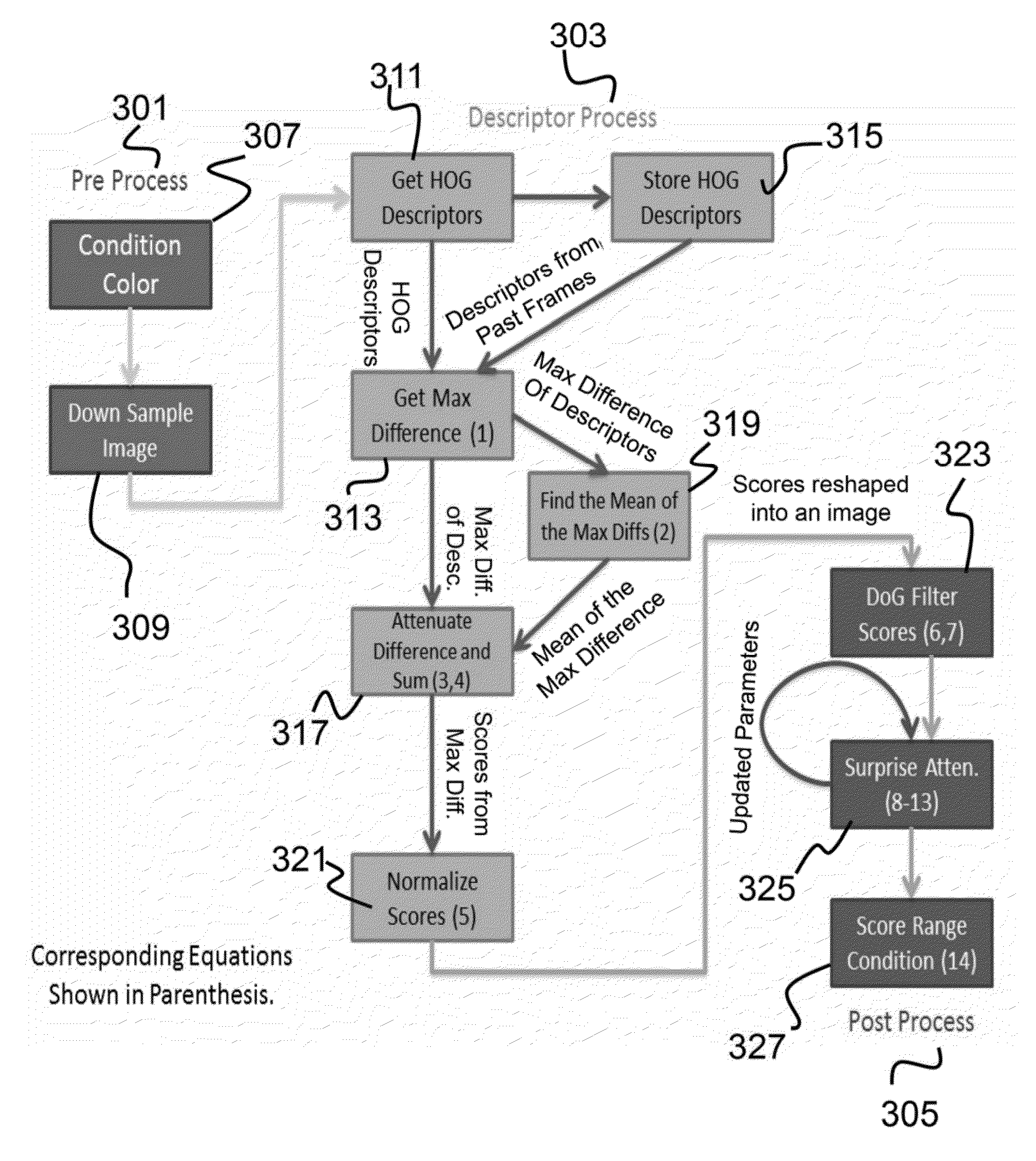
[0027]The present invention relates to an object detection system and, more particularly, to a scene change detection system that identifies regions of interest in an input frame while reducing the effect of motion noise. The following description is presented to enable one of ordinary skill in the art to make and use the invention and to incorporate it in the context of particular applications. Various modifications, as well as a variety of uses in different applications will be readily apparent to those skilled in the art, and the general principles defined herein may be applied to a wide range of aspects. Thus, the present invention is not intended to be limited to the aspects presented, but is to be accorded the widest scope consistent with the principles and novel features disclosed herein.

[0028]In the following detailed description, numerous specific details are set forth in order to provide a more thorough understanding of the present invention. However, it will be apparent t...


PUM


Abstract

Described is a system for scene change detection. The system receives an input image (current frame) from a video stream. The input image is color conditioned to generate a color conditioned image. A sliding window is used to segment the input image into a plurality boxes. Descriptors are extracted from each box of the color conditioned image. Thereafter, differences in the descriptors are identified between a current frame and past frames. The differences are attenuated to generate a descriptor attenuation factor αi. Initial scores are generated for each box based on the descriptor attenuation factor αi. The initial scores are filtered to generate a set of conspicuity scores for each box, the set of conspicuity scores being reflective of the conspicuity of each box in the image. Finally, the conspicuity scores are presented to the user or provided to other systems for further processing.

Description

GOVERNMENT RIGHTS[0001]This invention was made with government support under U.S. Government Contract Number PO 154318, the REF ASPS Program. The government has certain rights in the invention.CROSS-REFERENCE TO RELATED APPLICATIONS[0002]This is a non-provisional patent application of U.S. Provisional Application No. 61 / 780,561, filed on Mar. 13, 2013, and entitled, “Device for outdoor scene change detection from conspicuity of histogram of oriented gradient based features with adaptive Bayesian.”FIELD OF INVENTION[0003]The present invention relates to an object detection system and, more particularly, to a scene change detection system that identifies regions of interest in an input frame while reducing the effect of motion noise.BACKGROUND OF INVENTION[0004]The present invention is directed to a scene change detection system which can be used for object detection. Scene change detection is often referred to as motion conspicuity detection. While motion conspicuity detectors exist,...

Claims


Application Information

Patent Timeline
IPC IPC(8): H04N9/64H04N5/14H04N11/20
CPCH04N5/147H04N11/20G06T7/254G06T7/90
Inventor MUNDHENK, TERRELL N.FLORES, A. ARTURO
Owner HRL LAB
Why Eureka
Eureka Blog
Learn More