
Locomotive LED/optics headlight assembly

a headlight assembly and led/optic technology, applied in the direction of fixed installation, lighting and heating equipment, lighting support devices, etc., can solve the problem of not meeting the regulations and the inability to install the assembly in a manner

Inactive Publication Date: 2015-01-13
J W SPEAKER CORP
View PDF4 Cites 5 Cited by
  • Summary
  • Abstract
  • Description
  • Claims
  • Application Information

AI Technical Summary

Benefits of technology

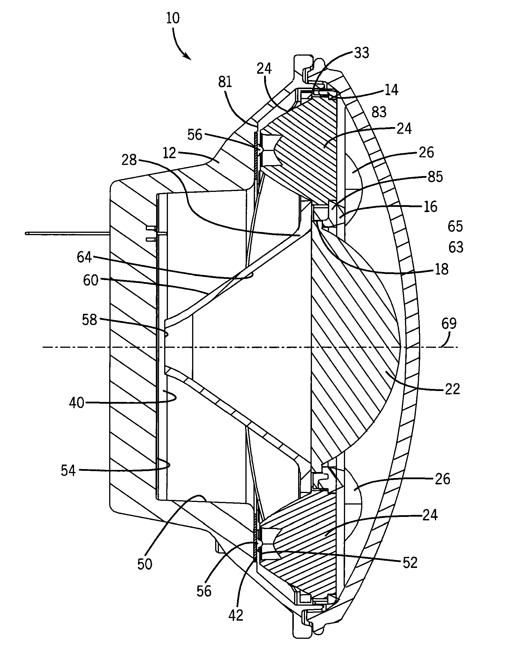
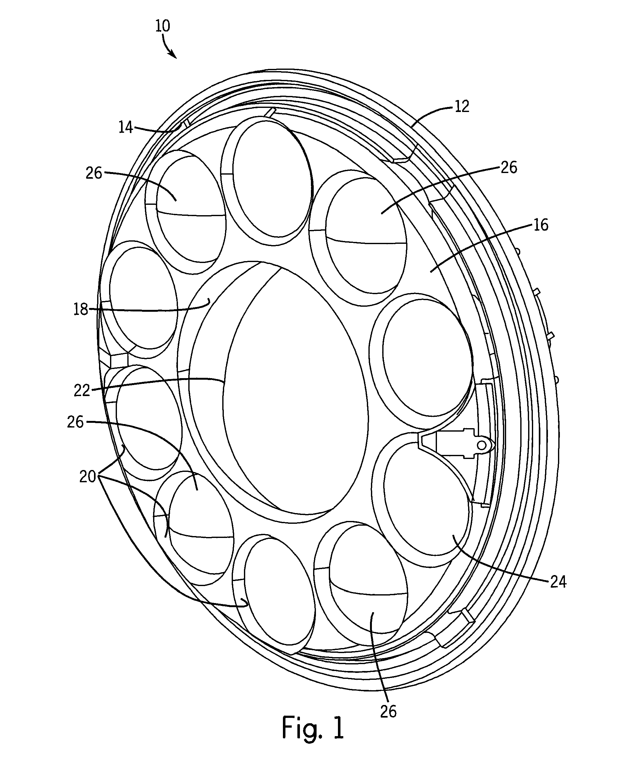
The patent describes a device that includes multiple light sources and lenses to create a bright light pattern within a low-luminance ring. The light sources are mounted in the chamber of the device and the lenses are placed in the opening. The lenses are aligned with the light sources to create the intense light pattern. This technology can be used for various applications such as lighting, decorative lighting, and photography.

Problems solved by technology

In this manner the design of the LED light assembly can render it impossible to install the assembly in a manner which does not meet regulations.

Method used


Image

  • Locomotive LED/optics headlight assembly
  • Locomotive LED/optics headlight assembly
  • Locomotive LED/optics headlight assembly

Examples


Embodiment Construction

[0035]The various aspects of the subject invention are now described with reference to the annexed drawings, wherein like reference numerals correspond to similar elements throughout the several views. It should be understood, however, that the drawings and detailed description hereafter relating thereto are not intended to limit the claimed subject matter to the particular form disclosed. Rather, the intention is to cover all modifications, equivalents, and alternatives falling within the spirit and scope of the claimed subject matter.

[0036]The word “exemplary” is used herein to mean serving as an example, instance, or illustration. Any aspect or design described herein as “exemplary” is not necessarily to be construed as preferred or advantageous over other aspects or designs.

[0037]Referring now to the drawings wherein like reference numerals correspond to similar elements throughout the several views and, more specifically, referring to FIGS. 1 through 7, at least some embodiment...


PUM


Abstract

A headlamp assembly comprising a housing forming an internal chamber and forming an opening to one side, at least a first light source having a first illumination axis, the first light source mounted in a central portion of the internal chamber substantially at a first depth, at least a second light source having a second illumination axis, the second light source mounted in a circumferential portion of the chamber substantially at a second depth wherein the first depth is greater than the second depth, a first aspherical lens formed about a first optic axis, the first aspherical lens mounted within the opening with the first optic axis aligned with the first illumination axis and a second aspherical lens formed about a second optic axis, the second aspherical lens mounted within the opening with the second optic axis aligned with the second illumination axis.

Description

CROSS-REFERENCE TO RELATED APPLICATIONS[0001]This application is based on U.S. provisional patent application Ser. No. 61 / 528,545 filed on Aug. 29, 2011 and entitled “LOCOMOTIVE LED / OPTICS HEADLIGHT ASSEMBLY”.STATEMENT REGARDING FEDERALLY SPONSORED RESEARCH OR DEVELOPMENT[0002]Not applicable.BACKGROUND OF THE INVENTION[0003]The present invention relates to locomotive headlights and more specifically to an LED type replacement headlight assembly that meets regulated light output requirements and still fits within a typical space allotted for a locomotive headlight.[0004]LED lighting uses less energy than incandescent type lighting, is more robust, and typically LED light sources last far longer than incandescent type sources. For this reason LED type lights are advantageous in many applications including industrial applications where work has to be halted when a light source fails. One application in which work has to be stopped when a light source fails is the locomotive headlight a...

Claims


Application Information

Patent Timeline
Patent Type & Authority Patents(United States)
IPC IPC(8): B61D29/00F21V5/04F21V7/04B61L15/02F21S8/10F21W107/10
CPCB61D29/00B61L15/02F21S48/1154F21S48/1275F21S48/1291F21W2101/02B61L2207/02F21S48/328F21S41/285F21S41/265F21S41/27F21W2107/10F21S45/48F21V13/04
Inventor KAY, BRADLEY WILLIAM
Owner J W SPEAKER CORP
Learn More